From Drawing to Production: How Landun Develops Custom Carbide Drills
Landun CNC Tool provides a structured custom carbide drill development service covering application analysis, drawing review, DFM evaluation, sample production, testing feedback and repeat batch manufacturing.
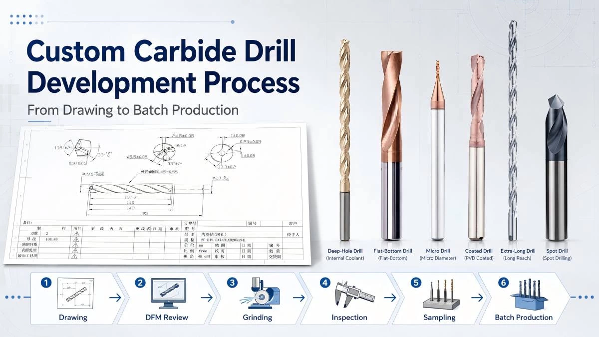
Why Some Drilling Applications Require a Custom Tool
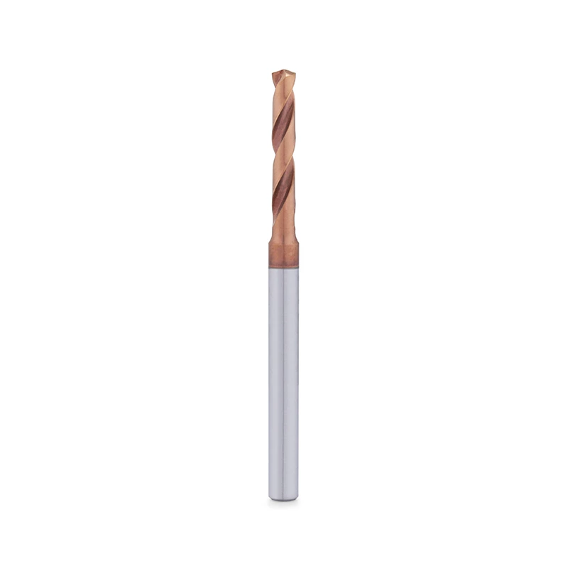
Standard solid carbide drills can meet many common holemaking requirements. However, they may not be the most efficient solution when a component contains special diameters, multiple steps, unusual hole depths or strict dimensional requirements.
A custom carbide drill is developed around the actual workpiece and machining conditions rather than being selected only according to a standard catalog size.
Typical reasons for developing a custom drill include:
- A non-standard hole diameter
- Multiple diameters in one hole
- A step, chamfer or counterbore feature
- A flat-bottom hole
- A special drill-point angle
- An extended flute or overall length
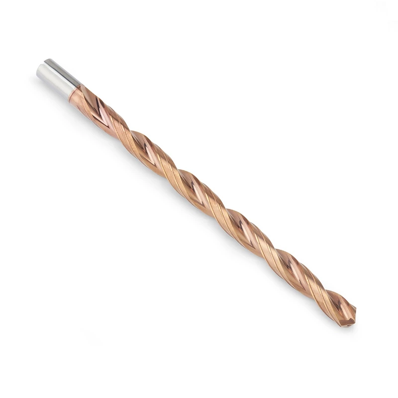
- Deep-hole drilling requirements
- Limited tool-changing time
- Poor chip evacuation with the current drill
- Insufficient tool life
- Unstable hole tolerance
- The need to combine several operations into one tool
For example, a component may currently require one drill for the pilot hole, another tool for the larger diameter and a third tool for chamfering.
A properly designed compound drill may combine these operations, helping reduce tool changes, machining time and positioning differences between separate processes.
However, combining operations also increases the importance of tool design. Each diameter, cutting section, transition and relief area must be coordinated according to the component drawing and machining sequence.
Step 1: Send the Drawing, Sample or Application Information
The custom drill development process begins with collecting accurate application information.
Customers can provide:
- A 2D engineering drawing
- A PDF drawing
- A STEP or STP file
- A 3D model
- A photograph of the workpiece
- A photograph of the existing drill
- A physical drill sample
- A machined component sample
- Basic hole dimensions and machining requirements
A complete drawing is usually the most efficient starting point because it shows the relationship between the hole features, tolerances and workpiece structure.
However, a project can also begin with a sample or application description when a formal drawing is not immediately available.
In addition to the drawing, customers should provide information about the machining conditions.
Important details include:
- Workpiece material
- Material grade
- Material hardness
- Hole diameter
- Hole depth
- Through hole or blind hole
- Required hole tolerance
- Required surface quality
- Machine type
- Spindle speed range
- Toolholder type
- Internal or external coolant
- Coolant pressure
- Current cutting parameters
- Current tool life
- Existing drilling problems
- Expected order quantity
This information helps the engineering team understand not only what geometry must be produced, but also how the drill will be used.
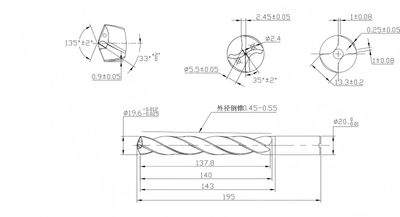
Step 2: Application Review and DFM Evaluation
After receiving the available technical information, Landun reviews the project from both machining and manufacturing perspectives.
This stage is commonly referred to as a Design for Manufacturing, or DFM, evaluation.
The purpose of the DFM review is to determine whether the requested drill can be manufactured reliably and whether the proposed structure is suitable for the intended drilling application.
The review may cover:
- Drill diameter and length
- Length-to-diameter ratio
- Number and position of steps
- Step lengths
- Point angle
- Flat-bottom or conventional point design
- Flute structure
- Core strength
- Margin design
- Coolant-hole requirements
- Shank dimensions
- Toolholder compatibility
- Coating requirements
- Inspection feasibility
- Required dimensional tolerance
For a deep-hole drill, the engineering team may focus on tool rigidity, chip evacuation and coolant delivery.
For a step drill, the relationship between each diameter and step length becomes especially important.
For a flat-bottom drill, the cutting-edge structure must support stable entry and controlled bottom formation.
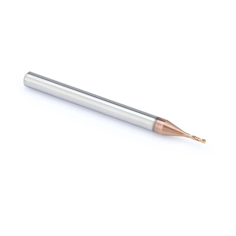
For a micro drill, runout sensitivity, edge strength and machine condition require additional attention.
A typical DFM evaluation can usually be completed within approximately three to five working days after sufficient technical information has been received.
The actual evaluation time may vary according to the complexity of the tool and whether additional information is required.
Step 3: Confirm the Tool Design
After the initial evaluation, Landun prepares or confirms the proposed custom drill design.
The technical communication may include:
- Main drill dimensions
- Cutting diameter
- Step diameters
- Flute length
- Overall length
- Shank diameter
- Point angle
- Step angle
- Chamfer dimensions
- Coolant-hole structure
- Coating option
- Special tolerance requirements
The design must balance several factors.
A longer tool may be necessary to reach the required hole depth, but increasing the tool length can reduce rigidity.
A larger flute space may improve chip evacuation, but the core must remain strong enough to resist bending and breakage.
A sharp cutting edge may reduce cutting resistance in some materials, while a stronger prepared edge may be required for more demanding or interrupted cutting conditions.
The final structure must therefore consider the complete drilling system rather than one isolated dimension.
Before sample manufacturing begins, the proposed drawing or technical specification should be confirmed by both sides.
This provides a clear reference for production, inspection and later modification.
Step 4: Select the Carbide, Geometry and Coating
Custom drill development is not limited to changing the outside dimensions of a standard drill.
The carbide substrate, cutting geometry and surface treatment must also be selected according to the application.
Carbide Substrate
The carbide grade influences:
- Cutting-edge strength
- Wear resistance
- Resistance to chipping
- Tool rigidity
- Performance in small-diameter tools
- Suitability for continuous or demanding cutting conditions
The appropriate balance depends on the workpiece material, drill diameter and machining environment.
Cutting Geometry
The drill geometry may be adjusted according to:
- Workpiece material
- Chip shape
- Hole depth
- Cutting resistance
- Required centering performance
- Coolant delivery
- Machine rigidity
The drill point, flute, core, margin and cutting edges must work together.
For example, a geometry intended for aluminum should support smooth chip evacuation and reduce material adhesion, while a drill for stainless steel must address cutting heat, work hardening and chip control.
Coating Selection
Coating may be selected according to the workpiece material, cutting temperature, friction conditions and required wear resistance.
The objective is not simply to change the appearance of the drill.
A suitable coating should complement the carbide substrate and geometry while supporting more stable performance under the intended machining conditions.
Step 5: Produce the First Sample
Once the design is confirmed, the project enters sample production.
The sample manufacturing process may include:
- Carbide blank preparation
- Production-program setup
- Five-axis precision grinding
- Cutting-edge preparation
- Dimensional inspection
- Coating or surface treatment
- Post-coating inspection
- Product identification
- Final sample verification
For many custom projects, sample production can typically be completed within approximately seven to ten working days after the design and commercial details have been confirmed.
Complex drill structures, special carbide blanks, unusual coolant-hole designs or specific coating requirements may require additional time.
The first sample is manufactured according to the confirmed technical information and is inspected before being sent for application testing.
Step 6: Test the Drill Under Actual Machining Conditions
A dimensional inspection confirms whether the sample matches the approved drawing, but actual cutting performance must be evaluated on the customer’s machine and workpiece.
Testing should be carried out under controlled conditions.
The customer should record:
- Spindle speed
- Feed rate
- Feed per revolution
- Drilling depth
- Coolant type
- Coolant pressure
- Toolholder condition
- Tool runout
- Number of holes completed
- Hole diameter
- Hole-position accuracy
- Hole surface condition
- Chip shape
- Tool wear
- Reason for tool replacement
Photographs or videos of the chips, drilled holes and worn cutting edges can also provide useful information.
The test results help determine whether the sample meets the required production target or whether further adjustment is necessary.
Step 7: Review Feedback and Optimize the Design
Not every custom drill reaches its final version after the first test.
This does not necessarily mean the initial design has failed. Custom tool development is often an optimization process in which sample results are used to improve the relationship between geometry, cutting parameters and actual machine conditions.
Common feedback may include:
- Chips are too long
- Chips remain inside the flute
- The drill produces excessive noise
- Hole diameter changes during the test
- The cutting edge wears too quickly
- The tool chips at the drill point
- The drill breaks before reaching the target life
- The flat-bottom surface is not stable
- Burr formation is excessive
- The drill enters the workpiece inaccurately
Depending on the test result, possible optimization directions may include:
- Adjusting the drill-point geometry
- Modifying the cutting-edge condition
- Changing the flute structure
- Strengthening the tool core
- Adjusting the margin
- Changing the coating option
- Revising the coolant outlet position
- Optimizing the cutting parameters
- Improving toolholder or runout control
The adjustment should be based on observable test evidence rather than changing several variables without a clear reason.
When possible, only the necessary factors should be modified between tests. This makes it easier to identify which change improves the drilling result.
Step 8: Approve the Final Sample and Drawing
When the sample reaches the required performance level, the customer confirms the final version.
The confirmed information may include:
- Final tool drawing
- Main dimensions
- Carbide option
- Coating option
- Tool geometry
- Inspection requirements
- Product marking
- Packaging requirements
- Approved cutting parameters
- Sample test results
The approved drawing becomes the main technical reference for future production.
This step is important because a custom drill must be repeatable. A successful sample provides limited value if later batches do not maintain the same dimensions and geometry.
The production and quality-control teams therefore require a clear, approved specification before entering regular batch manufacturing.
Step 9: Move from Sample to Batch Production
After sample approval, Landun can arrange batch production according to the confirmed drawing and order quantity.
A typical batch-production lead time is approximately two to four weeks, depending on:
- Tool complexity
- Order quantity
- Carbide blank availability
- Coating requirements
- Inspection requirements
- Packaging requirements
- Current production schedule
During batch manufacturing, the approved sample and drawing are used as production references.
Important dimensions and tool features are inspected according to the product structure and agreed requirements.
For repeat orders, retaining the approved technical information helps reduce communication time and supports more consistent reproduction of the tool.
Quality Control for Custom Carbide Drills
Custom tools often require more detailed inspection than standard catalog products because the dimensions and features are specific to one customer or component.
Depending on the tool structure, inspection may include:
- Cutting diameter
- Step diameter
- Step length
- Flute length
- Overall length
- Shank diameter
- Point angle
- Step angle
- Chamfer dimensions
- Drill-point symmetry
- Margin condition
- Coolant-hole position
- Cutting-edge condition
- Coating appearance
- Product marking
Inspection should be carried out at appropriate stages rather than relying only on a final visual check.
Before Coating
The main geometry and dimensions can be evaluated directly before the surface layer is applied.
This stage helps identify dimensional or grinding problems before the drill moves to the next process.
After Coating
The coating surface and cutting edges are checked to confirm that important features remain in the required condition.
Before Shipment
The final specification, quantity, marking, labels and packaging are checked against the customer’s order.
For repeat production, the batch can also be compared with the approved drawing and retained inspection information.
Typical Custom Carbide Drill Projects
Landun supports different types of non-standard carbide drill development.
Common projects include:
Custom Step Drills
Custom step drills can produce two or more diameters in one operation.
They may help reduce tool changes and improve the positional relationship between connected hole features.
Custom Flat-Bottom Drills
Flat-bottom drills can be developed for blind holes, flat seating surfaces, counterbores or components where a conventional conical drill point is unsuitable.
Custom Deep-Hole Drills
Deep-hole drills may require extended flute lengths, increased tool rigidity and internal coolant delivery.
The tool design must be coordinated with the machine, coolant pressure and drilling strategy.
Custom Compound Drills
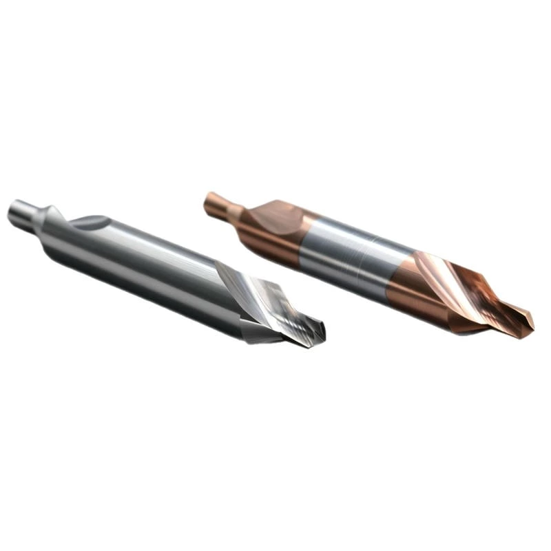
Compound drills may combine drilling, stepping, chamfering or other holemaking operations in one tool.
These tools can be useful in high-volume production where reducing cycle time is important.
Non-Standard Diameter Drills
A custom diameter may be required when the finished hole does not match a standard catalog size or when the hole allowance must suit a later machining process.
Drills for Specific Materials
Tool geometry and coating can also be developed according to materials such as:
- Carbon steel
- Stainless steel
- Aluminum alloy
- Cast iron
- Titanium alloy
- Tool steel
- Mold steel
- Other industrial materials
The material grade, hardness and machining condition should be provided during the initial evaluation.
What Information Should Be Included in an Inquiry?
Providing complete information at the beginning can shorten the evaluation process and reduce repeated communication.
A custom carbide drill inquiry should ideally include:
- Workpiece drawing
- Workpiece material and hardness
- Hole diameter
- Hole depth
- Through hole or blind hole
- Hole tolerance
- Required bottom or step geometry
- Machine model
- Toolholder type
- Coolant method
- Coolant pressure
- Current spindle speed and feed
- Current drill brand or structure
- Current tool life
- Main drilling problem
- Expected monthly or annual quantity
When some information is not available, customers can first send the drawing and describe the main machining problem.
The engineering team can then identify which additional details are required.
Confidential Technical Communication
Custom drill projects may involve component drawings, product structures and manufacturing information that are not intended for public distribution.
Technical files submitted for project evaluation are used to understand the application and prepare the corresponding drill solution.
Customers may also indicate any specific document-control or confidentiality requirements when submitting their project information.
Clear communication and controlled technical documentation help both sides develop the tool more efficiently.
Build a Repeatable Custom Drilling Solution
A custom carbide drill should not be treated as a one-time product with only the correct dimensions.
The objective is to develop a repeatable drilling solution that can be manufactured consistently and used under defined machining conditions.
By connecting application analysis, DFM evaluation, tool design, precision grinding, sample production, testing feedback and batch quality control, Landun CNC Tool supports customers from the initial drawing to repeat production.
Start Your Custom Carbide Drill Project
Customers can send Landun CNC Tool a drawing, 3D model, drill sample or basic application information for an initial technical evaluation.
To receive a more accurate assessment, include the workpiece material, hole dimensions, drilling depth, machine conditions, coolant method and current tooling problem.
The typical project process is:
Drawing or sample submission → Application evaluation → DFM review → Tool design → Sample production → Cutting test → Sample approval → Batch production
Contact Landun CNC Tool to discuss your custom carbide drill requirements.
 Need a Custom Tool solution?