How Landun Matches Carbide Drills to Material, Hole Depth and Cooling Conditions
Landun CNC Tool helps industrial customers select solid carbide drills according to workpiece material, hole depth, coolant method, machine conditions and production targets rather than relying on diameter alone.
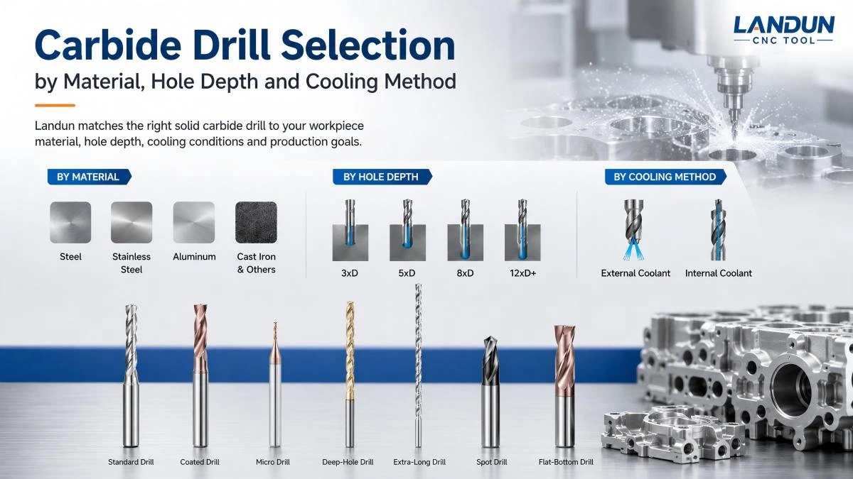
Carbide Drill Selection Requires More Than Choosing a Diameter
Selecting a carbide drill begins with the required hole diameter, but diameter alone does not determine whether a tool will perform reliably.
Two components may require the same hole size while creating completely different drilling conditions.
For example, a short through hole in aluminum does not place the same demands on a drill as a deep blind hole in stainless steel. A stable machining center with internal coolant also provides different operating conditions from a machine using external coolant.
The suitable drill must therefore be selected according to the complete application.
Important factors include:
- Workpiece material
- Material hardness
- Hole diameter
- Hole depth
- Through-hole or blind-hole structure
- Required tolerance
- Coolant method
- Coolant pressure
- Machine rigidity
- Spindle condition
- Toolholder condition
- Production quantity
- Target tool life
Landun CNC Tool evaluates these factors when recommending standard, micro, deep-hole, flat-bottom or custom carbide drills.
The objective is not simply to supply a drill that fits the required diameter. The objective is to match the drill structure to the actual cutting conditions.
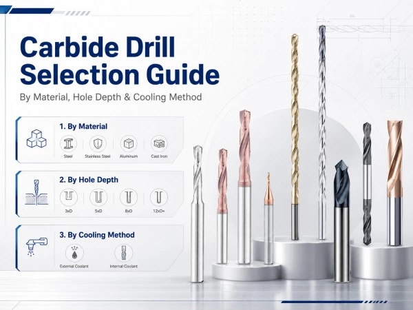
Selecting Carbide Drills by Workpiece Material
Different materials produce different cutting temperatures, chip shapes, cutting forces and wear mechanisms.
A drill geometry developed for one material may not provide the same result in another material.
The carbide substrate, drill point, flute structure, cutting-edge condition and coating should therefore be coordinated with the workpiece material.
Carbide Drills for Steel
Carbon steel, alloy steel and general engineering steel are widely used in automotive, machinery, mold components and general manufacturing.
Steel drilling applications may vary significantly according to material grade, hardness and heat-treatment condition.
Common requirements include:
- Stable drill-point entry
- Balanced cutting forces
- Controlled chip formation
- Reliable chip evacuation
- Consistent hole diameter
- Resistance to flank wear
- Stable performance in batch production
For short and medium-depth holes, standard solid carbide drills may provide an efficient solution.
Typical depth options may include:
- 3xD carbide drills
- 5xD carbide drills
- 8xD carbide drills
The appropriate depth ratio should be selected according to the actual hole depth rather than automatically choosing a longer drill.
A shorter tool generally provides greater rigidity. When the application only requires a shallow hole, using an unnecessarily long drill may increase sensitivity to runout and vibration.
For deeper holes, flute length, core strength, coolant delivery and chip evacuation must receive greater attention.
Carbide Drills for Stainless Steel
Stainless steel drilling presents different challenges from general steel drilling.
Many stainless steel grades generate high cutting heat, resist chip breaking and may work-harden when the cutting process becomes unstable.
Common drilling problems include:
- Long or tangled chips
- Chip adhesion
- Built-up material on the cutting edge
- Rapid edge wear
- Excessive cutting temperature
- Hole-diameter variation
- Premature drill chipping
- Work hardening at the hole entrance or bottom
A suitable carbide drill for stainless steel should support controlled cutting and efficient chip removal.
The drill geometry must provide sufficient cutting ability while maintaining the edge strength required for continuous production.
Coolant delivery also becomes important, particularly as the hole depth increases.
For relatively shallow holes, an external-coolant drill may be suitable when the machine and application provide effective coolant access.
For deeper holes, an internal-coolant drill can deliver coolant closer to the cutting zone and assist chip evacuation under suitable pressure conditions.
However, internal coolant alone does not guarantee stable drilling.
The coolant-hole design, flute structure, drilling parameters and machine conditions must work together.
For stainless steel applications, customers should provide:
- Stainless steel grade
- Material hardness
- Hole diameter
- Hole depth
- Through or blind hole
- Coolant method
- Current cutting parameters
- Current chip condition
- Existing tool-life problem
This information allows the drill structure and cutting conditions to be evaluated more accurately.
Carbide Drills for Aluminum
Aluminum alloys generally allow higher cutting speeds than steel, but they create their own drilling challenges.
The material may adhere to the cutting edge or flute surface, especially when chip evacuation, lubrication or cutting geometry is unsuitable.
Common aluminum drilling requirements include:
- Sharp and stable cutting edges
- Smooth chip evacuation
- Reduced material adhesion
- Sufficient flute space
- Controlled hole entrance
- Good hole-wall finish
- Reduced burr formation
A drill for aluminum should support the removal of soft and potentially adhesive chips without allowing them to accumulate inside the flute.
Surface condition is especially important.
A smooth flute can help reduce friction and support chip movement, while suitable cutting geometry can reduce unnecessary deformation of the material.
For short holes in stable machining conditions, an external-coolant carbide drill may be sufficient.
For deeper holes or higher production volumes, internal coolant may improve chip removal and temperature control.
The final selection should consider the aluminum grade, hole depth, machine speed, lubrication and required surface quality.
Carbide Drills for Cast Iron
Cast iron produces shorter chips than many steels, but it can create abrasive wear.
The drill must maintain cutting-edge stability while resisting the wear caused by graphite, hard particles and the specific cast structure.
Important considerations include:
- Cast iron grade
- Material consistency
- Surface condition
- Presence of casting skin
- Hole depth
- Interrupted cutting
- Required hole tolerance
- Dry or coolant-assisted machining
Gray cast iron, ductile iron and other cast materials do not behave identically.
For example, casting skin or interrupted surfaces can increase impact on the drill point and cutting edges.
The drill geometry and edge condition should therefore be selected according to the actual component rather than based only on the general material name “cast iron.”
In some applications, dry or near-dry drilling may be considered, while other production conditions may use coolant.
The selected drill and machining parameters must match the customer’s actual production environment.
Carbide Drills for Titanium and Other Difficult Materials
Titanium alloys and other difficult-to-machine materials may produce high localized cutting temperatures and place considerable stress on the cutting edge.
These applications require careful control of:
- Cutting speed
- Feed rate
- Drill-point geometry
- Cutting-edge strength
- Coolant delivery
- Tool runout
- Pecking strategy, when necessary
- Chip evacuation
- Tool wear
Titanium drilling should not be approached by simply reducing all cutting parameters without analysis.
Insufficient feed may cause rubbing instead of efficient cutting, while excessive heat can accelerate tool wear.
Because titanium applications vary by alloy grade, component structure and hole depth, Landun evaluates these projects according to the actual machining information.
Application-specific or custom drills may be considered when a standard product cannot provide the required stability.
Selecting Carbide Drills by Hole Depth
Hole depth has a direct influence on drill rigidity, chip evacuation, coolant delivery and cutting stability.
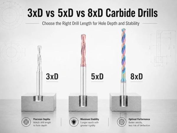
The length-to-diameter ratio is commonly expressed as xD.
For example, a 5xD drill is designed for a drilling depth of approximately five times the drill diameter, subject to the tool design and recommended application conditions.
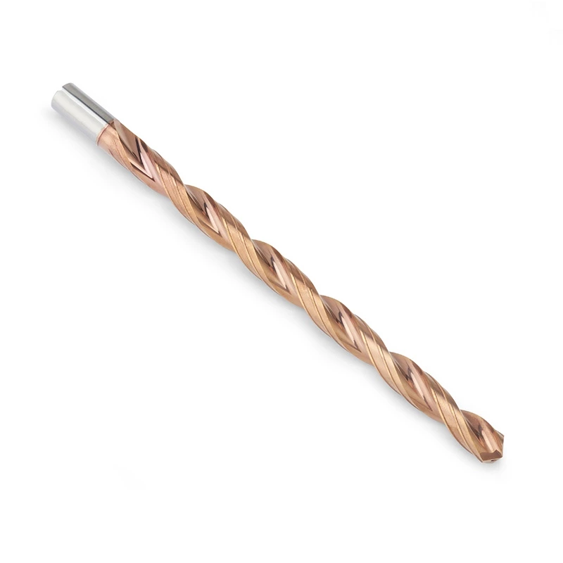
Landun supplies and develops carbide drills for different depth ranges, including:
- 3xD
- 5xD
- 8xD
- 12xD
- 15xD
- 20xD
- 30xD and application-specific depths
The correct selection should provide enough usable drilling length without introducing unnecessary overhang.
3xD Carbide Drills
A 3xD carbide drill is commonly used for relatively shallow holes.
Its shorter structure generally provides good rigidity and may reduce sensitivity to deflection compared with longer tools.
Typical applications include:
- General component holes
- Shallow blind holes
- Through holes in thin or medium components
- Batch drilling in stable setups
- Applications with limited chip-travel distance
When the required drilling depth is within the usable range of a 3xD drill, selecting a significantly longer tool may not provide an advantage.
5xD Carbide Drills
A 5xD drill provides additional reach while maintaining a relatively stable tool structure.
It can be used for many medium-depth drilling applications in steel, stainless steel, aluminum and cast iron.
The selection between external and internal coolant depends on:
- Material
- Hole depth
- Chip shape
- Machine capability
- Coolant access
- Production volume
A 5xD drill is a common option when a 3xD tool does not provide enough flute length but a deep-hole drill is not yet required.
8xD Carbide Drills
At approximately 8xD, chip evacuation and coolant access become more critical.
The tool has a longer cutting section and is more sensitive to:
- Runout
- Machine vibration
- Toolholder accuracy
- Incorrect entry
- Inadequate coolant
- Chip accumulation
Internal coolant is often useful for suitable 8xD applications because it delivers coolant closer to the drill point.
However, the available coolant pressure and flow must be sufficient for the drill diameter and hole depth.
12xD to 20xD Deep-Hole Drills
As drilling depth increases beyond standard ranges, the drill must maintain stability over a longer distance.
Deep-hole drilling may require:
- A pilot or guide hole
- Controlled tool entry
- Internal coolant
- Suitable coolant pressure
- Stable spindle and toolholder
- Reduced runout
- Appropriate cutting parameters
- Reliable chip evacuation
- A defined entry and retraction procedure
The recommended process may differ according to the drill design.
Some deep-hole drills are intended to enter a pilot hole before reaching operating speed, while other structures may use different entry conditions.
Customers should follow the recommended operating method for the selected tool.
30xD and Special Deep-Hole Drills
Very deep holes create greater challenges in chip removal, coolant delivery and tool stability.
At these depths, the complete machining system must be evaluated.
Important information includes:
- Machine model
- Spindle condition
- Toolholder type
- Maximum coolant pressure
- Coolant filtration
- Pilot-hole dimensions
- Hole orientation
- Workpiece setup
- Material grade
- Required hole straightness
- Required cycle time
A 30xD or application-specific deep-hole drill should not be selected only from a catalog image.
Technical evaluation is recommended before confirming the tool structure and cutting process.
Selecting Between Internal and External Coolant
Cooling method is another important factor in carbide drill selection.
Both external-coolant and internal-coolant drills can perform effectively when used in suitable conditions.
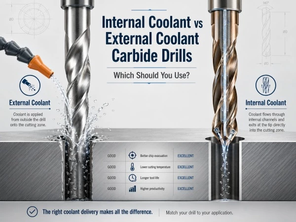
External-Coolant Carbide Drills
External coolant is supplied from outside the tool toward the drilling area.
Advantages may include:
- Simpler machine requirements
- Suitable performance in shallow holes
- Lower tool complexity
- Easy application on machines without through-spindle coolant
- Practical use in general drilling
External coolant is generally more effective when the drilling zone remains accessible.
As the drill moves deeper into the hole, the workpiece can restrict coolant access to the cutting zone.
This may make chip evacuation and heat control more difficult.
Internal-Coolant Carbide Drills
Internal-coolant drills contain coolant channels that direct fluid through the tool toward the drill point.
Potential benefits include:
- Coolant delivery closer to the cutting edges
- Improved chip movement
- Better temperature control
- Greater suitability for deeper holes
- More consistent support in batch drilling
The effectiveness of internal coolant depends on more than the presence of coolant holes.
The machine must provide suitable:
- Coolant pressure
- Coolant flow
- Filtration
- Toolholder connection
- Spindle sealing
- Coolant quality
Small-diameter coolant channels are particularly sensitive to contamination and inadequate filtration.
Customers should confirm machine capability before selecting an internal-coolant drill.
Through Holes and Blind Holes Require Different Considerations
A through hole allows the drill point and chips eventually to exit the opposite side of the workpiece.
A blind hole ends inside the component.
These two structures can create different machining requirements.
Through-Hole Drilling
For through holes, important considerations include:
- Breakthrough stability
- Exit burrs
- Reduced support near the hole exit
- Chip evacuation
- Drill-point clearance
- Protection of fixtures or components behind the workpiece
The drill may experience a change in cutting load as it exits the material.
Suitable cutting conditions and workpiece support can help control the breakthrough stage.
Blind-Hole Drilling
For blind holes, the drill must stop at a controlled depth without breaking through the workpiece.
Important factors include:
- Hole depth
- Drill-point allowance
- Bottom shape
- Chip accumulation
- Coolant access
- Required flatness
- Distance from internal component features
A conventional drill point produces a conical hole bottom.
When the application requires a flatter bottom, a flat-bottom drill or custom drill structure may be more appropriate.
Standard, Micro, Deep-Hole or Custom Drill?
Landun organizes carbide drill solutions according to the actual application.
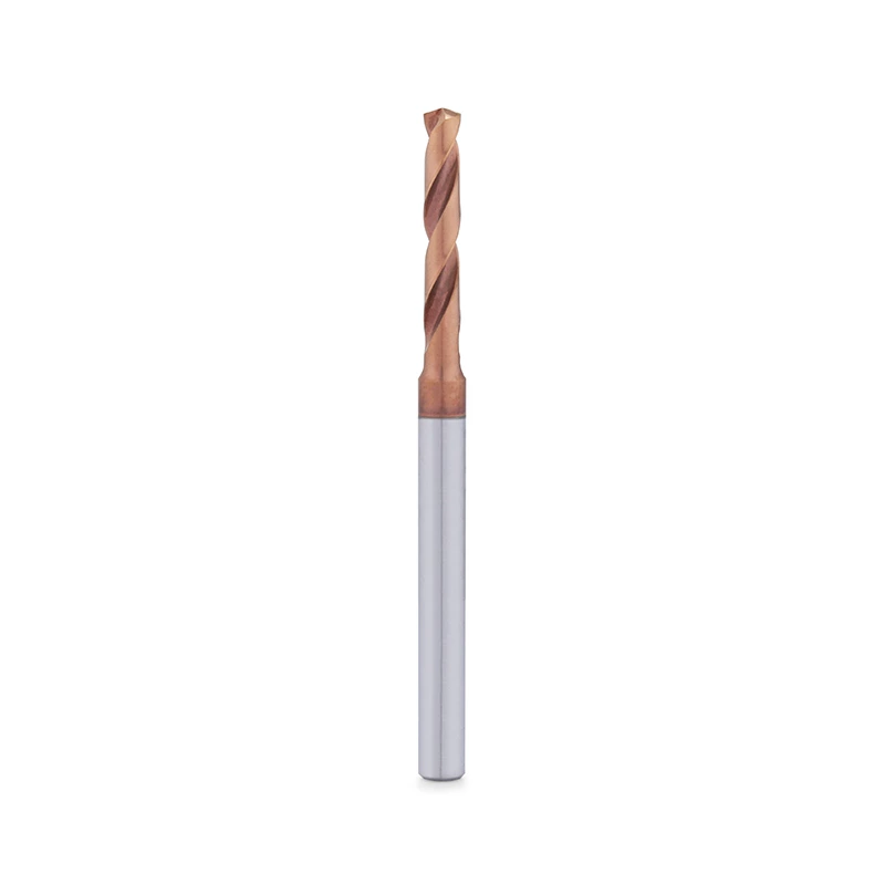
Choose a Standard Carbide Drill When:
- The diameter is a common catalog size
- The hole depth is within a standard range
- The component has a conventional hole structure
- Standard geometry is suitable for the material
- No special step or bottom profile is required
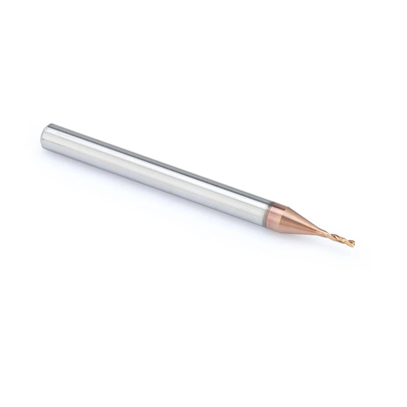
Choose a Micro Carbide Drill When:
- The hole diameter is very small
- The component requires precision micro holes
- Runout and cutting-edge condition must be tightly controlled
- The machine and toolholder are suitable for micro drilling
Choose a Deep-Hole Carbide Drill When:
- The drilling depth exceeds standard length ranges
- Chip evacuation becomes a major concern
- Internal coolant is available
- The machine can support a controlled deep-hole process
- Hole straightness and depth consistency are important
Choose a Custom Carbide Drill When:
- The diameter is non-standard
- Several diameters must be produced in one operation
- The hole requires a step or chamfer
- A flat bottom is required
- Standard drills do not provide sufficient tool life
- Multiple processes need to be combined
- The workpiece structure creates a special entry condition
- A specific coolant or length design is required
Information Required for a Drill Recommendation
To recommend a suitable carbide drill, Landun needs more than a diameter and quantity.
Customers are encouraged to provide:
- Workpiece material
- Material grade
- Material hardness
- Hole diameter
- Hole depth
- Through hole or blind hole
- Required tolerance
- Required hole-bottom shape
- Machine model
- Spindle interface
- Toolholder type
- Internal or external coolant
- Coolant pressure
- Current spindle speed
- Current feed rate
- Existing drill type
- Current tool life
- Chip condition
- Main drilling problem
- Expected order quantity
When available, customers can also provide:
- Workpiece drawings
- Hole drawings
- STEP or STP files
- 3D models
- Photographs of the component
- Photographs of the worn drill
- Videos of the drilling process
- Chip photographs
Clear application information helps reduce trial-and-error selection and allows the technical team to identify whether a standard or custom drill is more appropriate.
Matching the Drill to the Complete Machining System
A carbide drill does not operate independently.
Its performance is affected by the complete machining system, including:
- Machine rigidity
- Spindle condition
- Toolholder accuracy
- Tool runout
- Workpiece clamping
- Coolant delivery
- Cutting parameters
- Hole-entry condition
- Operator procedure
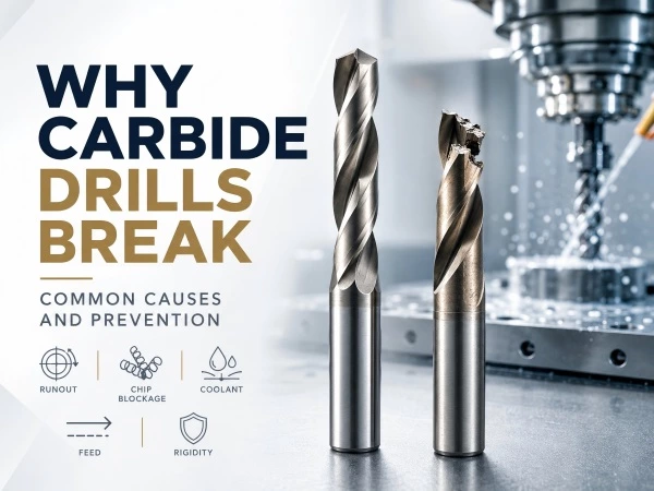
Even a correctly designed drill may perform poorly if runout is excessive, the toolholder is worn or chips cannot leave the hole.
For this reason, tool selection and application analysis should be considered together.
When a drilling problem occurs, the drill itself should be inspected, but the machine, holder, coolant and cutting process should also be reviewed.
Landun Carbide Drill Solutions
Landun CNC Tool supplies and develops carbide drills for different materials, hole depths and cooling conditions.
Available product structures include:
- Standard solid carbide drills
- Micro carbide drills
- Deep-hole carbide drills
- Internal-coolant drills
- External-coolant drills
- Flat-bottom drills
- Step drills
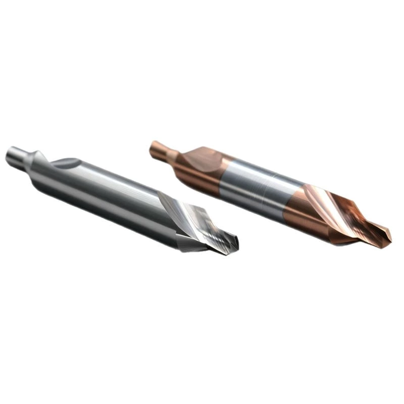
- Spot drills
- Center drills
- Double-ended drills
- Custom compound drills
By organizing drill selection according to material, depth, cooling and hole structure, Landun helps customers identify a more suitable starting point for technical evaluation.
Discuss Your Drilling Application with Landun
Customers can send Landun CNC Tool their workpiece drawing, material information, hole dimensions and machining conditions for drill selection or custom-tool evaluation.
For a more accurate recommendation, please include:
Material → Hole diameter → Hole depth → Through or blind hole → Machine → Coolant method → Current parameters → Current drilling problem
Contact Landun CNC Tool to discuss the suitable carbide drill for your application.
 Need a Custom Tool solution?