Inside Landun CNC Tool: Precision Carbide Drill Manufacturing and Quality Control
Landun CNC Tool combines precision grinding, cutting-edge preparation, coating and systematic inspection to support consistent solid carbide drill quality from sample development to repeat batch production.
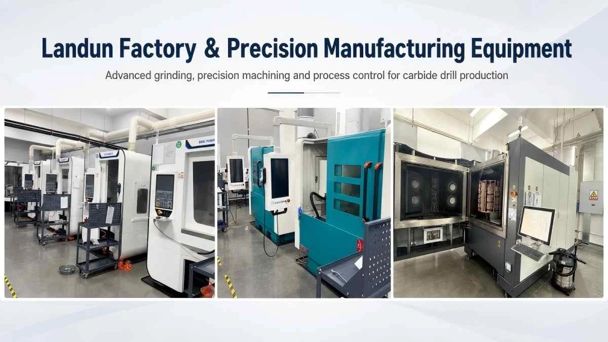
Precision Manufacturing Behind Every Carbide Drill
A solid carbide drill may appear to be a relatively simple cutting tool, but its performance depends on the accuracy of several closely connected features.
The drill point must enter the workpiece steadily. Both cutting edges must share the cutting load evenly. The flute must provide enough space for chip evacuation, while the core must remain strong enough to resist bending and breakage. The margin, relief surface and cutting-edge condition must also match the intended workpiece material and drilling conditions.
Small variations in these features may affect:
- Hole-position accuracy
- Hole-diameter consistency
- Chip evacuation
- Cutting stability
- Tool wear
- Hole surface quality
- Repeatability during batch production
For this reason, carbide drill manufacturing requires coordinated control throughout the production process rather than relying on one final inspection.
At Landun CNC Tool, the manufacturing process may include carbide blank preparation, geometry design, five-axis grinding, cutting-edge preparation, coating, dimensional inspection and final quality verification.
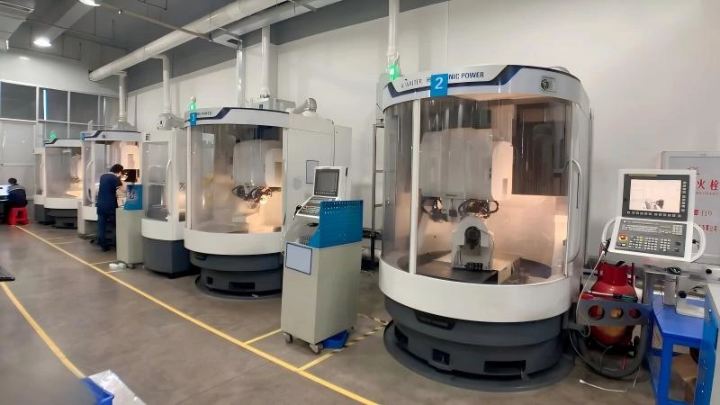
Five-Axis Grinding for Critical Drill Geometry
Precision grinding is one of the most important stages in solid carbide drill manufacturing.
Landun uses Walter five-axis grinding machines to produce and control critical drill features such as:
- Drill-point geometry
- Helical flutes
- Cutting edges
- Margins and lands
- Primary and secondary relief surfaces
- Core transitions
- Cutting-section lengths
- Special step and compound structures
Five-axis grinding makes it possible to coordinate multiple tool features within one controlled manufacturing process.
This is particularly important for drill-point symmetry. When the two main cutting edges are not properly balanced, one side may carry more of the cutting load than the other. This can contribute to vibration, uneven wear, hole-position deviation or premature tool failure.
Accurate grinding also helps maintain the intended relationship between the flute, core, margin and relief geometry. These features must work together to provide both cutting efficiency and structural strength.
Manufacturing Different Carbide Drill Structures
Carbide drills are not manufactured according to one universal geometry.
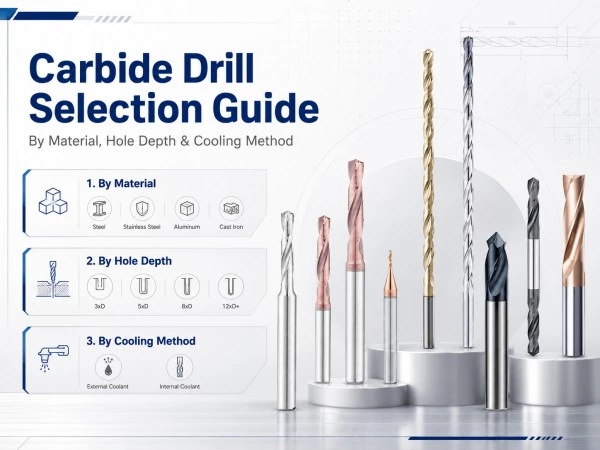
Tool structure must be selected according to factors such as:
- Workpiece material
- Material hardness
- Hole diameter
- Drilling depth
- Through-hole or blind-hole design
- Machine rigidity
- Spindle condition
- Internal or external cooling
- Required hole tolerance
- Target tool life
Landun manufactures and develops different drill structures for standard and application-specific holemaking requirements.
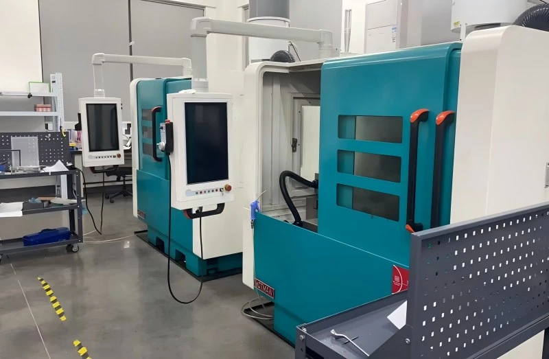
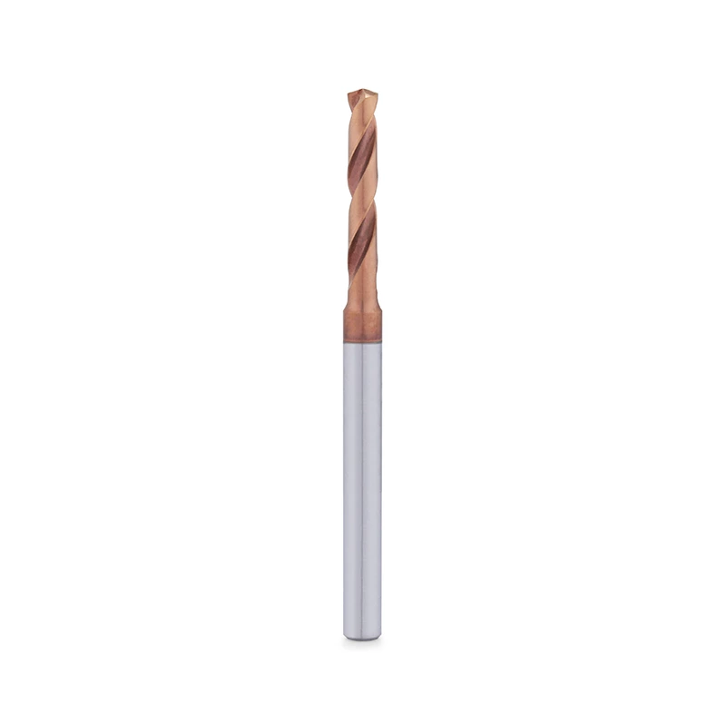
Standard Solid Carbide Drills
Standard carbide drills are commonly used for general holemaking in steel, stainless steel, aluminum, cast iron and other engineering materials.
Although their structure is relatively conventional, stable performance still requires accurate control of the drill point, flute profile, margin, core thickness and cutting-edge condition.
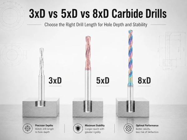
Standard drills may be produced in different drilling-depth ratios, such as 3xD, 5xD and 8xD, depending on the hole depth and machining conditions.
As the length-to-diameter ratio increases, tool rigidity and chip evacuation become more important.
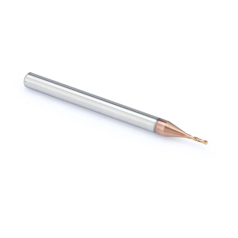
Micro Carbide Drills
Micro carbide drills are used for small-diameter holes in precision components, electronics, medical parts and other applications where dimensional control is especially important.
Because the cutting section is small, micro drills are more sensitive to:
- Tool runout
- Cutting-edge damage
- Uneven cutting load
- Machine vibration
- Incorrect feed
- Poor chip evacuation
The manufacturing process must therefore control both the cutting geometry and the integrity of the small cutting section.
Even a minor edge defect that would have limited influence on a larger drill may significantly affect the performance of a micro drill.
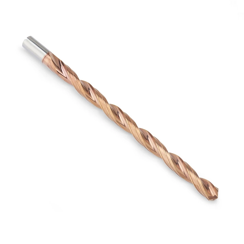
Deep-Hole Carbide Drills
Deep-hole drilling presents additional challenges because chips must travel a longer distance before leaving the hole.
As the drilling depth increases, the tool must maintain sufficient rigidity while also providing a stable path for chip evacuation and coolant delivery.
Deep-hole carbide drills may require careful control of:
- Flute shape
- Core strength
- Overall tool length
- Cutting-section length
- Margin design
- Drill-point structure
- Coolant-hole position
- Surface condition
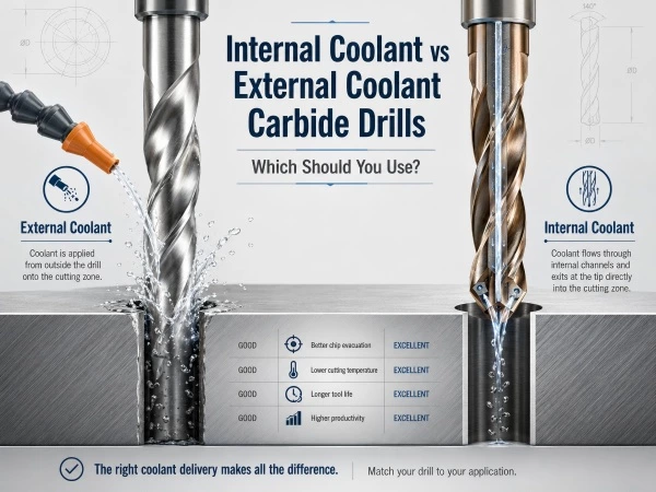
Internal-coolant designs can deliver coolant closer to the cutting zone, helping to control cutting temperature and assist chip evacuation under suitable machining conditions.
However, the drill structure, coolant pressure, machine condition and drilling parameters must be evaluated together.
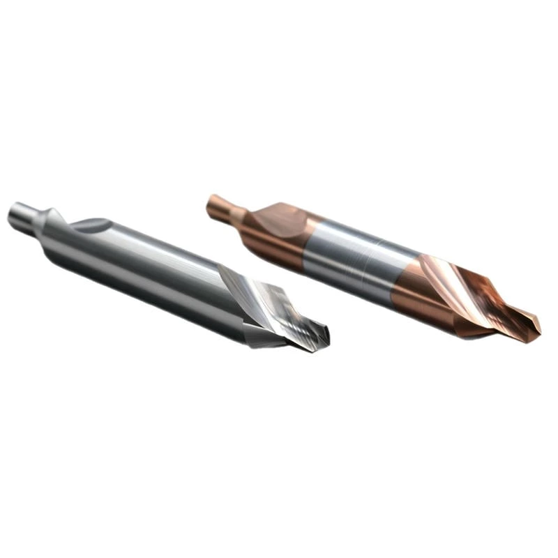
Flat-Bottom, Step and Special Drills
Flat-bottom drills, step drills and compound drills may contain multiple diameters, cutting sections, angles or transitions.
These tools are often used to combine several holemaking operations or produce a specific hole profile more efficiently.
Their manufacturing accuracy depends not only on each individual dimension, but also on the relationship between those dimensions.
For example, a custom step drill may need to control:
- First cutting diameter
- Second cutting diameter
- Step length
- Step angle
- Overall drilling depth
- Chamfer dimensions
- Flat-bottom geometry
- Position of internal coolant outlets
Accurate coordination of these features helps the finished tool produce the required hole profile consistently.
Cutting-Edge Preparation Before Coating
Grinding produces the basic cutting geometry, but the condition of the cutting edge must also be evaluated before coating.
A newly ground carbide edge may contain microscopic irregularities that cannot be judged reliably by the naked eye.
Controlled cutting-edge preparation can help improve edge consistency and reduce isolated weak points along the cutting edge.
The required edge condition depends on the application.
A very sharp edge may reduce cutting resistance in some materials, but it may also be more sensitive to localized damage. A stronger prepared edge may improve resistance to chipping, but excessive preparation may increase cutting load.
The suitable balance must therefore be selected according to:
- Workpiece material
- Material hardness
- Drill diameter
- Drill-point geometry
- Cutting speed
- Feed rate
- Cooling conditions
- Required tool life
Cutting-edge preparation should support the intended drilling application rather than being applied as the same fixed process to every drill.
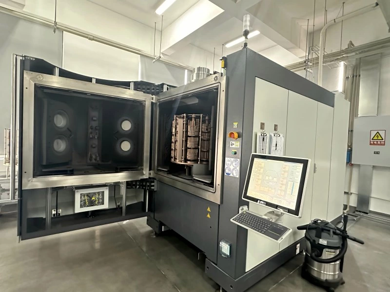
Coating and Surface Treatment
Coating selection is based on the interaction between the carbide substrate, drill geometry, workpiece material and cutting conditions.
Different applications generate different combinations of heat, friction, adhesion and abrasive wear. A coating suitable for drilling steel may not be the best option for aluminum, stainless steel or another engineering material.
The coating process may include:
- Tool cleaning
- Surface preparation
- Tool fixture arrangement
- Coating process control
- Surface-condition inspection
- Cutting-edge inspection after coating
- Product identification
For suitable drilling applications, coating can help improve wear resistance, reduce friction and maintain more stable tool performance.
However, coating alone cannot correct inaccurate drill geometry.
The drill point, flute, margin, cutting edge, carbide substrate and coating must function as a complete cutting system.
Quality Inspection at Key Production Stages
Quality control should not begin only after all manufacturing processes have been completed.
At Landun CNC Tool, dimensional and cutting-edge inspection is carried out at important stages of production according to the product structure and order requirements.
Walter HELICHECK PLUS and high-magnification inspection systems are used to evaluate tool dimensions, drill-point geometry, cutting-edge condition and surface quality.
Commonly inspected features may include:
- Drill diameter
- Shank diameter
- Flute length
- Overall length
- Drill-point angle
- Drill-point symmetry
- Margin condition
- Relief geometry
- Step diameter
- Step position
- Cutting-edge condition
- Coating appearance
- Product marking
Inspection Before Coating
Before coating, the basic tool dimensions and ground geometry can be evaluated directly.
This stage helps identify dimensional, geometric or cutting-edge issues before the tools proceed to coating.
Depending on the drill type, inspection may focus on the outside diameter, flute length, drill point, margin, relief surface and special structural dimensions.
For custom drills, the inspection standard should correspond to the confirmed tool drawing.
Inspection After Coating
After coating, the tool surface and cutting edges are checked again.
The purpose is to confirm that the coating appearance is consistent and that important cutting features remain in the required condition.
The inspection may include:
- Surface uniformity
- Visible coating defects
- Cutting-edge condition
- Drill-point appearance
- Product color and identification
- Overall cleanliness
Coated tools that do not meet the required visual or edge-condition standard should be separated before packaging.
Final Verification Before Shipment
The final verification stage confirms that the finished products correspond to the order requirements.
This may include checking:
- Product model
- Diameter and length
- Quantity
- Coating option
- Product marking
- Label information
- Packaging requirements
- Custom drawing reference
For repeat orders, production and inspection information can be compared with the previously approved specification.
This helps reduce differences between the confirmed sample and later batch production.
From Sample Development to Repeat Production
A successful sample is only the first stage of an industrial carbide drill project.
For many customers, the more important question is whether the same drill geometry and performance can be reproduced in later batches.
Repeatability is especially important in:
- Automotive component manufacturing
- Aerospace component machining
- Mold and die production
- Medical component manufacturing
- Electronics production
- Precision mechanical engineering
- High-volume metalworking
After a sample is evaluated and approved, important product information can be retained as a reference for subsequent production.
This information may include:
- Approved tool drawing
- Main product dimensions
- Drill-point structure
- Flute and margin requirements
- Carbide and coating option
- Workpiece material
- Recommended application conditions
- Inspection requirements
- Sample-testing feedback
- Product marking and packaging details
Documenting the approved specification helps the manufacturing and inspection teams maintain a consistent reference when the tool enters repeat production.
Supporting Custom Carbide Drill Development
Standard drills can meet many general holemaking requirements, but some applications require a tool developed for a specific component, hole structure or production target.
Landun supports custom carbide drill development based on customer drawings, samples and machining information.
Custom projects may include:
- Non-standard drill diameters
- Special flute lengths
- Extended overall lengths
- Stepped diameters
- Flat-bottom structures
- Special point geometries
- Internal-coolant designs
- Compound drilling and chamfering tools
- Tools for specific workpiece materials
- Tools designed to replace several separate operations
To evaluate a project efficiently, customers are encouraged to provide:
- Workpiece drawing
- Workpiece material and hardness
- Hole diameter and depth
- Through-hole or blind-hole information
- Required tolerance
- Machine type
- Toolholder information
- Spindle speed range
- Coolant method and pressure
- Current cutting parameters
- Existing tool-life problems
- Expected production quantity
Technical files may be supplied as PDF drawings, STEP or STP files, 3D models, engineering plans, JPG images or sample photographs.
The available information helps the engineering team evaluate the tool structure, manufacturing feasibility and suitable production process.
Manufacturing Capability Focused on Drilling Results
Advanced equipment is valuable only when it supports the required machining result.
The objective of carbide drill manufacturing is not simply to produce a tool with the correct external appearance. The tool must provide the geometry, consistency and structural strength required for the actual drilling application.
By connecting tool design, five-axis grinding, cutting-edge preparation, coating and inspection, Landun CNC Tool supports both standard carbide drill supply and application-specific tool development.
This integrated process helps customers address requirements related to:
- Hole accuracy
- Cutting stability
- Chip evacuation
- Tool-life consistency
- Batch-production reliability
- Special hole profiles
- Reduced machining operations
Work with Landun CNC Tool
Landun CNC Tool provides standard, micro, deep-hole and custom solid carbide drills for different materials and drilling conditions.
Customers can send a drawing, sample or basic application information for technical evaluation.
To receive a more accurate recommendation or quotation, please include the workpiece material, hole dimensions, drilling depth, machine conditions, coolant method, required tolerance and estimated order quantity.
Contact Landun CNC Tool to discuss your carbide drilling application and custom tool requirements.
 Need a Custom Tool solution?