Why Carbide Drills Break: 10 Common Causes and How to Prevent Them
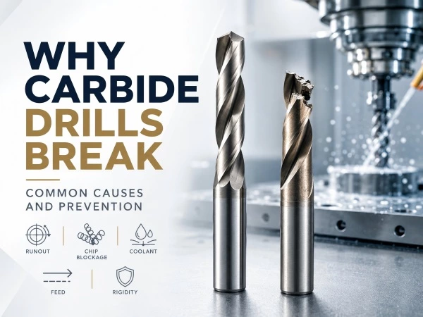
Carbide drills provide high rigidity, wear resistance and stable hole quality in CNC production, but they are less tolerant of bending, impact and unstable cutting conditions than HSS drills. Understanding where and why failure begins is essential for preventing repeated drill breakage.
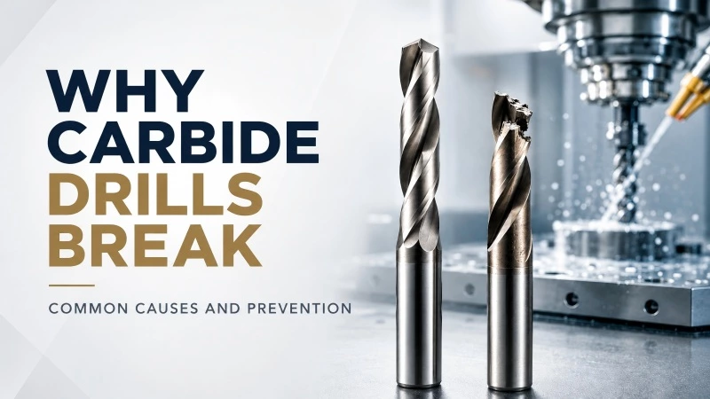
A carbide drill often appears to break suddenly, but the actual cause may have been developing over several holes. Uneven wear, excessive runout, restricted chip evacuation or insufficient coolant can gradually increase the load on the cutting edges until the tool chips or fractures.
Replacing the broken drill without identifying the underlying cause may only repeat the same failure. Effective troubleshooting requires reviewing the complete drilling system, including the drill, toolholder, machine, workpiece, coolant and cutting parameters.
Why Carbide Drill Breakage Requires Systematic Troubleshooting
Solid carbide is highly rigid and wear resistant. These characteristics allow a carbide drill to maintain its geometry under stable CNC machining conditions.
However, carbide does not tolerate bending and impact in the same way as high-speed steel.
A carbide drill may fail when it is exposed to:
-
Unequal cutting loads
-
Excessive radial runout
-
Sudden impact
-
Chip blockage
-
Inadequate coolant
-
Excessive tool overhang
-
Unstable workpiece clamping
-
Incorrect speed or feed
-
Damaged cutting edges
-
Improper entry or breakthrough conditions
The visible fracture is therefore not always the original problem.
For example, a drill may break because chips become packed inside the flutes, but the chip blockage may have been caused by insufficient feed, poor coolant flow or an unsuitable flute design.
Troubleshooting should identify the first abnormal condition rather than focusing only on the final breakage.
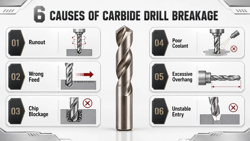
1. Excessive Tool Runout
Runout is one of the most common causes of uneven carbide drill wear and premature failure.
When the drill does not rotate concentrically, one cutting edge removes more material than the other. This creates unequal cutting forces.
Possible results include:
-
Uneven cutting-edge wear
-
Oversized holes
-
Poor hole position
-
Increased vibration
-
Margin damage
-
Cutting-edge chipping
-
Sudden drill breakage
The effect of runout becomes more serious as the drill becomes longer or smaller in diameter.
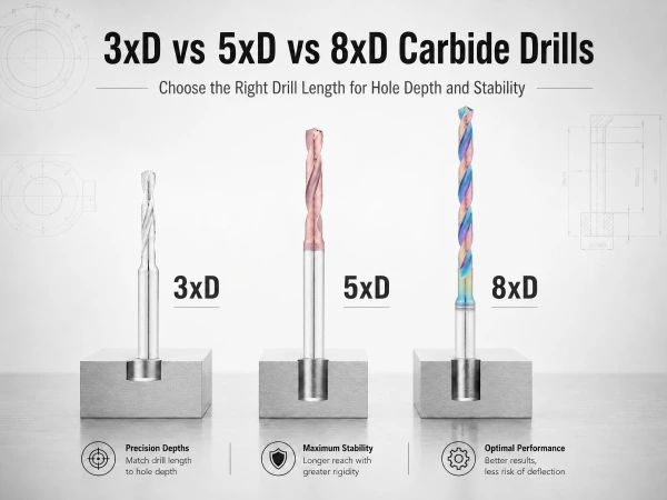
An 8xD drill is generally more sensitive to toolholder error than a 3xD drill of the same diameter. Micro drills are also highly sensitive because a small amount of runout represents a larger percentage of the drill diameter.
Common Sources of Runout
Runout may be caused by:
-
Dirt inside the toolholder
-
Chips on the drill shank
-
A worn collet
-
A damaged hydraulic chuck
-
Incorrect tool clamping
-
Insufficient clamping length
-
Spindle wear
-
A damaged drill shank
-
Excessive tool overhang
The drill, holder and spindle should be inspected as one system.
How to Reduce Runout
Useful actions include:
-
Clean the drill shank and holder before assembly
-
Inspect the collet or chuck for wear
-
Use a precision toolholder suitable for carbide drilling
-
Clamp the drill by the designed shank area
-
Minimize unnecessary overhang
-
Measure runout close to the cutting section
-
Inspect the machine spindle when repeated errors occur
Runout should be checked before increasing cutting parameters or replacing the drill with a different coating.
2. Incorrect Feed Rate
Feed rate has a direct influence on chip formation and cutting-edge load.
A feed that is too high can overload the cutting edges. A feed that is too low can cause the drill to rub instead of cutting efficiently.
Feed Rate Is Too High
Excessive feed may cause:
-
Cutting-edge chipping
-
High spindle load
-
Drill-point damage
-
Poor hole entry
-
Margin wear
-
Sudden fracture
-
Workpiece movement
The risk increases when the drill is long, the machine is not rigid or the material is hard.
Feed Rate Is Too Low
Very low feed may appear safer, but it can also create problems.
Possible results include:
-
Rubbing instead of cutting
-
Excessive heat
-
Work hardening in stainless steel
-
Poor chip formation
-
Accelerated edge wear
-
Built-up material
-
Unstable hole size
A carbide drill should form controlled chips rather than continuously rubbing against the workpiece.
How to Correct the Feed
Feed should be selected according to:
-
Drill diameter
-
Workpiece material
-
Material hardness
-
Drill geometry
-
Hole depth
-
Machine rigidity
-
Coolant method
-
Manufacturer recommendations
When troubleshooting, adjust the feed gradually and observe chip shape, spindle load and cutting-edge wear.
3. Incorrect Cutting Speed
Cutting speed affects temperature, wear and material behavior at the cutting edge.
A speed that is too high may generate excessive heat and accelerate wear. A speed that is too low may create unstable cutting, material adhesion or built-up edge.
Cutting Speed Is Too High
Possible symptoms include:
-
Rapid flank wear
-
Discoloration of chips
-
Coating deterioration
-
Edge softening in unsuitable conditions
-
Built-up heat near the drill point
-
Short tool life
High speed becomes especially risky when coolant cannot reach the cutting zone effectively.
Cutting Speed Is Too Low
Possible symptoms include:
-
Material adhesion
-
Built-up edge
-
Poor surface finish
-
Increased cutting forces
-
Unstable chips
-
Rubbing
The correct speed depends on the actual workpiece material and hardness, not only the general material category.
For example, two stainless steel grades may require different cutting conditions even though both are described as stainless steel.
4. Poor Chip Evacuation
A drill produces chips at the bottom of an enclosed hole. Those chips must travel upward through the flutes while the drill continues moving deeper into the workpiece.
When chips cannot leave the hole, they may become compressed between the drill and the hole wall.
Possible consequences include:
-
Rapid torque increase
-
Scratched hole walls
-
Margin damage
-
Cutting-edge chipping
-
Drill seizure
-
Hole-diameter variation
-
Sudden breakage
Chip evacuation becomes more difficult as hole depth increases.
A 3xD hole has a shorter chip path than an 8xD or 12xD hole. This is why longer drilling applications require greater attention to flute design, coolant delivery and chip formation.
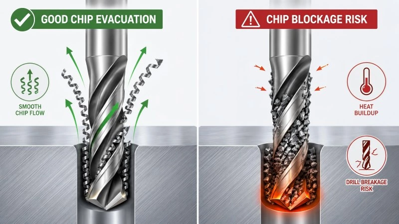
Signs of Chip Blockage
Common warning signs include:
-
Chips wrapping around the drill
-
Chips remaining inside the flutes
-
Increasing spindle load during depth
-
Irregular cutting noise
-
Coolant failing to return from the hole
-
Scratched or damaged hole walls
-
Broken chips packed around the drill point
How to Improve Chip Evacuation
Possible improvements include:
-
Use the correct feed to produce manageable chips
-
Select a drill geometry suitable for the material
-
Use internal coolant when required
-
Confirm sufficient coolant flow
-
Select the shortest suitable drill
-
Inspect the flutes for damage
-
Avoid using a worn drill
-
Review the drilling cycle
-
Use a dedicated deep-hole drill for long holes
Peck drilling should not be introduced automatically. Some solid carbide drills are designed for continuous drilling, and unnecessary pecking may create repeated impact or thermal cycling. The operating method should match the specific drill design.
5. Insufficient Coolant Delivery
Coolant helps control heat, lubricate the cutting area and transport chips out of the hole.
A large amount of visible coolant outside the workpiece does not guarantee that enough fluid reaches the drill point.
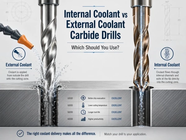
External coolant may lose effectiveness as the hole becomes deeper. Internal coolant can deliver fluid closer to the cutting edges, but it still requires sufficient flow, pressure and filtration.
Common Coolant Problems
Coolant-related failure may be caused by:
-
Poor nozzle position
-
Insufficient coolant flow
-
Inadequate coolant pressure
-
Blocked internal channels
-
Poor filtration
-
Incorrect coolant concentration
-
Leakage through the toolholder
-
Coolant supply interruption
-
Coolant not reaching the bottom of the hole
External-Coolant Applications
For shallow holes, the coolant nozzle should be directed toward the tool axis and hole entrance.
The stream should remain stable at the operating spindle speed.
Coolant that strikes the side of the holder or workpiece may not reach the cutting zone effectively.
Internal-Coolant Applications
For internal-coolant drills, confirm:
-
Through-spindle coolant is functioning
-
The holder is correctly sealed
-
Internal channels are clean
-
Filtration is appropriate
-
Flow remains stable
-
Coolant exits from the drill point
Small-diameter drills are especially sensitive to blocked coolant channels.
6. Using a Drill That Is Longer Than Necessary
A longer drill provides additional reach, but it also reduces rigidity and increases sensitivity to runout.
Using an 8xD drill for a 2xD hole may create unnecessary risk without improving the drilling result.
Excessive length can contribute to:
-
Tool deflection
-
Vibration
-
Hole-position error
-
Uneven edge loading
-
Poor surface quality
-
Increased breakage risk
The shortest drill that safely reaches the required depth should normally be selected.
Typical guidance includes:
-
Use 3xD for shallow holes
-
Use 5xD for medium-depth holes
-
Use 8xD only when the additional reach is required
-
Use a dedicated deep-hole drill beyond the standard depth range
Overall tool length should not be confused with usable drilling depth. The flute length and drill-point allowance must also be considered.
7. Unstable Tool Entry
The drill point should enter the workpiece under stable and balanced conditions.
A flat surface generally provides the most predictable entry. Angled, curved, rough or interrupted surfaces can cause one cutting edge to contact the workpiece before the other.
This creates an unbalanced load that may deflect or chip the drill.
Problematic entry conditions include:
-
Angled surfaces
-
Curved surfaces
-
Casting skin
-
Interrupted surfaces
-
Existing partial holes
-
Uneven workpiece edges
-
Cross-hole intersections
-
Incorrect pilot holes
Possible Solutions
Depending on the application, possible solutions include:
-
Machine a flat starting surface
-
Use a spot drill
-
Use a drill designed for angled entry
-
Reduce entry speed according to the tool recommendation
-
Use a pilot hole when required
-
Improve workpiece positioning
-
Use a custom drill geometry
A spot drill should have a suitable point angle and diameter for the following drill. An incorrectly prepared starting hole can guide the carbide drill unevenly and damage the corners.
8. Poor Machine or Workpiece Rigidity
Carbide drills require a stable machining system.
Even a correctly selected drill may fail when the workpiece moves or the machine vibrates.
Possible rigidity problems include:
-
Weak workpiece clamping
-
Thin unsupported walls
-
Worn machine components
-
Spindle vibration
-
Loose fixtures
-
Excessive tool overhang
-
Flexible toolholders
-
Unstable machine tables
Movement during drilling changes the load on the cutting edges and may cause intermittent impact.
How to Improve Rigidity
Possible actions include:
-
Reduce unnecessary tool overhang
-
Strengthen workpiece support
-
Inspect fixture contact points
-
Move the drill closer to the holder
-
Use a more rigid holder
-
Inspect spindle condition
-
Reduce unsupported workpiece areas
-
Check machine alignment
Changing the drill coating will not solve a mechanical rigidity problem.
9. Worn or Damaged Cutting Edges
A carbide drill should be replaced or reconditioned before wear reaches a level that creates unstable cutting forces.
Continuing to use a worn drill may cause:
-
Increased spindle load
-
Poor hole size
-
Excessive burrs
-
Higher temperature
-
Margin damage
-
Chipping
-
Catastrophic failure
Wear does not always appear equally on both cutting edges.
Uneven wear may indicate:
-
Runout
-
Poor alignment
-
Unbalanced coolant delivery
-
Workpiece movement
-
Incorrect geometry
-
Damage during handling
Inspecting the Drill
Inspection should focus on:
-
Main cutting edges
-
Drill corners
-
Chisel edge
-
Margins
-
Flute surfaces
-
Coating condition
-
Point symmetry
-
Signs of material adhesion
A drill that appears acceptable to the naked eye may still contain small edge chips. Magnified inspection can help detect early damage.
10. Incorrect Drill Geometry for the Workpiece Material
A universal drill cannot provide optimal performance in every material.
Different materials require different combinations of:
-
Drill-point geometry
-
Rake angle
-
Flute shape
-
Core thickness
-
Margin design
-
Cutting-edge preparation
-
Surface treatment
-
Coating
A drill designed for aluminum may prioritize sharp cutting edges and smooth chip evacuation. A drill for stainless steel may require stronger edge support and controlled chip formation.
Using unsuitable geometry may cause:
-
Material adhesion
-
Long chips
-
Excessive cutting forces
-
Poor centering
-
Rapid wear
-
Edge chipping
-
Chip blockage
The workpiece material should be identified as accurately as possible.
“Steel” or “stainless steel” alone may not provide enough information. Material grade, hardness and heat-treatment condition can affect drill selection.
11. Incorrect Pilot-Hole or Deep-Hole Procedure
Long drills and dedicated deep-hole drills may require a controlled entry process.
Depending on the tool design, this may include:
-
Preparing a pilot hole
-
Entering the pilot hole at reduced speed
-
Reaching the recommended depth before increasing speed
-
Activating internal coolant before cutting
-
Maintaining continuous feed
-
Reducing speed before retraction
A pilot hole can create problems when it is:
-
Misaligned
-
Too large
-
Too small
-
Too shallow
-
Too deep
-
Produced with an unsuitable point angle
-
Produced with poor surface quality
The pilot drill and long drill should be compatible.
The operating procedure should follow the requirements of the selected deep-hole drill rather than relying on one method for every long tool.
12. Breakage During Hole Breakthrough
The cutting load changes when a drill exits a through hole.
As the drill point breaks through the bottom surface, the workpiece provides less support and the cutting edges may engage unevenly.
Potential problems include:
-
Exit chipping
-
Large burrs
-
Sudden load changes
-
Drill grabbing
-
Workpiece movement
-
Cutting-edge damage
Breakthrough becomes more difficult when:
-
The exit surface is angled
-
The workpiece is thin
-
The material is soft or ductile
-
The fixture is unstable
-
Feed is excessive
-
The drill exits into another feature
The drilling program, fixture support and exit condition should be reviewed when failures consistently occur near the end of a through hole.
Where Did the Carbide Drill Break?
The fracture location can provide clues about the original cause.
Breakage at the Drill Point
Possible causes include:
-
Excessive feed
-
Hard inclusions
-
Unstable entry
-
Incorrect pilot hole
-
Edge damage
-
Material mismatch
-
Excessive runout
Breakage Along the Flute
Possible causes include:
-
Chip packing
-
Excessive torque
-
Poor coolant flow
-
Deep-hole instability
-
Recutting trapped chips
-
Incorrect drilling cycle
Breakage Near the Shank or Neck
Possible causes include:
-
Excessive bending
-
Too much overhang
-
Workpiece movement
-
Severe runout
-
Toolholder problems
-
Side loading
Breakage During Retraction
Possible causes include:
-
Chips trapped around the drill
-
Spindle stopped before full retraction
-
Coolant stopped too early
-
Incorrect retract speed
-
Hole-wall contact
-
Workpiece movement
Breakage During Breakthrough
Possible causes include:
-
Sudden load change
-
Excessive feed
-
Insufficient workpiece support
-
Angled exit surface
-
Large exit burr
-
Interrupted cutting
The fracture location does not provide a complete diagnosis, but it helps narrow the inspection process.
Carbide Drill Breakage Troubleshooting Table
| Symptom | Possible cause | Recommended check |
|---|---|---|
| One edge wears faster | Excessive runout | Check holder, spindle and clamping |
| Chips remain in flutes | Poor evacuation | Check feed, geometry and coolant |
| Breakage at hole entry | Unstable entry | Check surface, centering and alignment |
| Breakage at full depth | Chip packing or heat | Check coolant flow and chip condition |
| Hole becomes oversized | Runout or worn margins | Measure tool runout and inspect wear |
| Rapid corner chipping | Excessive load or impact | Review feed, entry and material |
| Repeated breakage at same depth | Workpiece feature or chip blockage | Review drawing and hole condition |
| Drill breaks during retraction | Trapped chips | Review coolant and retract procedure |
| Tool life varies widely | Unstable setup | Check holder, coolant and workpiece clamping |
| High spindle load | Excessive feed or chip packing | Inspect chips and cutting parameters |
A Step-by-Step Troubleshooting Process
When a carbide drill breaks, avoid changing several variables at the same time.
A structured process is more effective.
Step 1: Record the Failure
Document:
-
Drill diameter
-
Drill length
-
Hole depth
-
Workpiece material
-
Material hardness
-
Cutting speed
-
Feed
-
Coolant method
-
Number of holes completed
-
Exact point of failure
Step 2: Inspect the Broken Drill
Check:
-
Fracture location
-
Cutting-edge wear
-
Margin wear
-
Chip adhesion
-
Coating condition
-
Flute damage
-
Uneven wear
Step 3: Inspect the Chips
Chip shape can reveal whether the drill is cutting normally.
Look for:
-
Long tangled chips
-
Powder-like chips
-
Burned chips
-
Unequal chips from both edges
-
Thick compressed chips
-
Chips stuck in the flutes
Step 4: Check Runout and Clamping
Measure tool runout and inspect:
-
Toolholder cleanliness
-
Collet condition
-
Clamping length
-
Spindle accuracy
-
Drill shank damage
Step 5: Confirm Coolant Delivery
Check whether coolant reaches the cutting zone.
For internal coolant, confirm that fluid exits through all drill-point outlets.
Step 6: Review the Program
Verify:
-
Spindle speed
-
Feed rate
-
Feed units
-
Hole depth
-
Drill-point allowance
-
Entry method
-
Peck cycle
-
Retraction method
-
Breakthrough conditions
Step 7: Change One Factor at a Time
Changing the drill, holder, speed, feed and coolant simultaneously makes it difficult to identify the real problem.
Make controlled adjustments and record the result.
Pre-Production Checklist
Before starting a drilling batch, confirm:
-
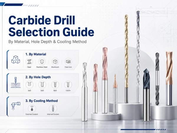
The drill matches the workpiece material
-
The drill length matches the hole depth
-
The drill is not damaged
-
The toolholder is clean
-
Runout is within an acceptable range
-
The workpiece is securely clamped
-
Coolant reaches the cutting zone
-
Internal channels are clear
-
Cutting parameters match the drill
-
The entry surface is suitable
-
The programmed depth is correct
-
Chip evacuation has been considered
-
The drill replacement limit is defined
A short setup inspection can prevent repeated tool failure and workpiece damage.
Frequently Asked Questions
Why does a carbide drill break without visible warning?
Carbide is highly rigid and may fracture after small chips, uneven wear or chip blockage have already increased the load. Regular inspection and spindle-load monitoring can help identify problems earlier.
Is low feed safer for a carbide drill?
Not always. Feed that is too low may cause rubbing, heat and work hardening. The drill must form stable chips.
Can too much coolant break a carbide drill?
The coolant itself normally does not break the tool, but unstable delivery, thermal shock in certain interrupted conditions, poor filtration or unsuitable pressure and flow may affect the process.
Why does the drill break at the same hole depth every time?
This often indicates chip accumulation, a hidden workpiece feature, a change in material condition or inadequate coolant delivery at that depth.
Should a carbide drill always use a peck cycle?
No. Many carbide drills are designed for continuous drilling. The correct cycle depends on the drill design, material, hole depth and coolant conditions.
Why does one cutting edge wear faster?
Uneven wear commonly indicates tool runout, poor alignment, uneven coolant delivery or unstable clamping.
Can a broken carbide drill be reground?
A broken drill is normally unsuitable for standard regrinding. A worn but unbroken drill may be professionally reground if enough material remains and the geometry can be restored.
Does a more expensive drill prevent breakage?
Tool quality matters, but even a high-quality drill can fail when runout, coolant, chip evacuation or cutting parameters are incorrect.
Conclusion
Carbide drill breakage is rarely caused by one factor alone.
The most common causes include:
-
Excessive runout
-
Incorrect feed or speed
-
Poor chip evacuation
-
Insufficient coolant
-
Excessive drill length
-
Unstable entry
-
Weak machine or fixture rigidity
-
Worn cutting edges
-
Unsuitable drill geometry
-
Incorrect deep-hole procedures
The most effective prevention strategy is to evaluate the complete drilling system.
The drill, holder, spindle, fixture, coolant, program and workpiece must operate together under stable conditions.
When a failure occurs, record the conditions, inspect the fracture location and change one factor at a time. This approach is more reliable than replacing the drill without correcting the original cause.
Discuss Your Carbide Drilling Problem
Landun CNC Tool supplies standard, micro, internal-coolant, deep-hole and custom solid carbide drills for different materials and hole depths.
Customers can provide the workpiece material, hole diameter, hole depth, machine information, coolant method, cutting parameters and photographs of the damaged drill for technical evaluation.
 Need a Custom Tool solution?