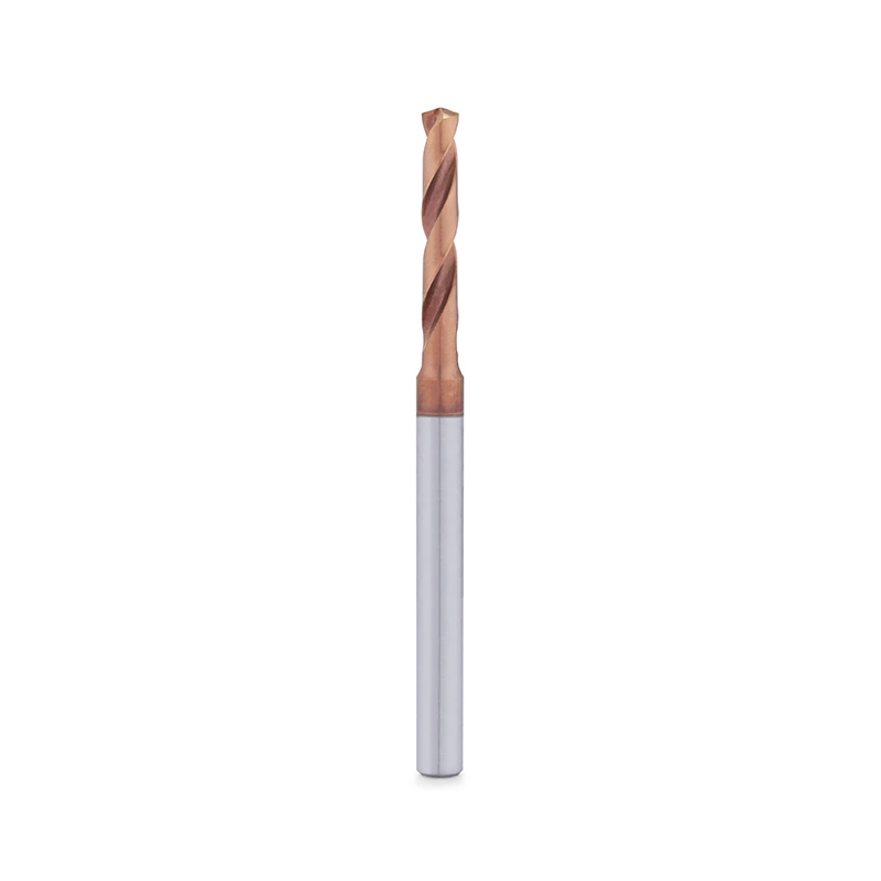
Deep Hole Drilling with Solid Carbide Drills: A CNC Process Guide
A practical guide to selecting and setting up solid carbide deep-hole drills, from pilot compatibility to coolant delivery and aluminum chip control.
What Is Deep Hole Drilling with Solid Carbide Drills?
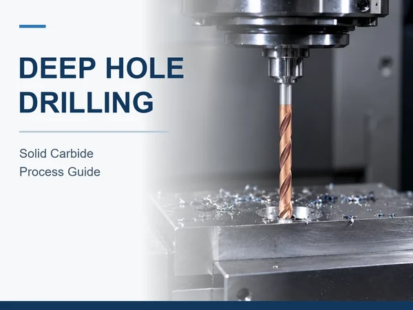
Deep hole drilling produces holes with a large depth relative to their diameter. For solid carbide twist drills on CNC machines, the extended reach makes entry guidance, chip evacuation and coolant access central to tool selection. This guide covers those twist-drill applications; gun drilling and BTA drilling use different tooling and coolant systems.
Tool length alone does not determine whether a deep-hole setup will work. Hole diameter, full-diameter depth, material grade, tolerance and exit geometry determine which drill configuration fits the application and how the tool is guided into the cut.
Two holes with the same diameter and depth may need different setups. A flat entry into solid material differs from an angled entry or a hole that crosses an internal passage. These features affect guidance and cutting load even when the required drill length is unchanged.
How Hole Depth Relates to Drill Diameter and Usable Length
The hole depth-to-diameter ratio equals full-diameter hole depth divided by hole diameter. For example, 100 mm of full-diameter depth divided by a 5 mm diameter gives a ratio of 20:1, also written as 20xD. This calculation describes the hole; it does not by itself establish that a particular 20xD drill meets the drawing.
Full-diameter depth differs from the deepest point left by the drill tip. In a blind hole, the tip extends beyond the cylindrical portion. Flute length, overall length and stated usable drilling depth describe different tool dimensions, so flute length alone does not establish whether a drill can produce the drawing's required depth.
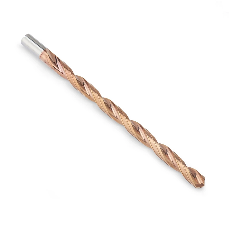
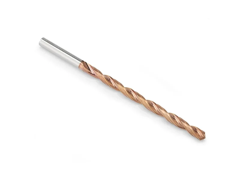
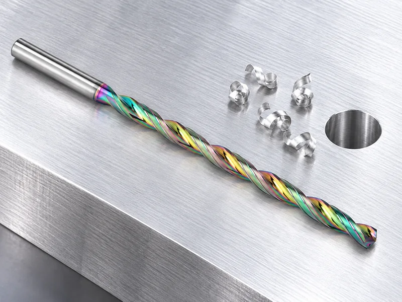
LANDUN's deep-hole carbide drill range covers selection beyond the standard series' usable depth. The required reach includes the hole depth and approach clearance, while the tool's flute arrangement must also allow chips to leave the hole. Excess length adds unsupported reach without helping when a shorter configuration already meets those requirements.
When Should You Consider a Different Drilling Process?
Solid carbide twist drills, gun drills and BTA systems use different tool and coolant arrangements. Their application ranges depend on hole diameter, depth, straightness requirements, machine configuration and production quantity. A program or pressure recommendation for one system does not establish the conditions for another.
Solid carbide twist drills can suit CNC deep-hole applications within the selected tool family's reach and process capability. Where the drawing requires a depth or straightness outside that range, a dedicated deep-hole process may be the appropriate production route.
Why Pilot Compatibility Matters During Entry
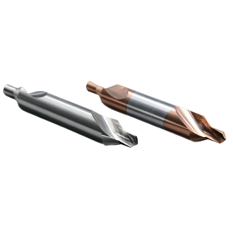
Before the margins are guided by the hole, an unsupported long drill can deflect during entry. A compatible pilot hole establishes the entry axis for drill families that require one. A shallow spot is not automatically an adequate substitute.
Pilot diameter, depth and bottom geometry affect how the long drill is supported and how its cutting edges first contact the material. An incompatible pilot can leave the tool poorly guided or cause one part of its cutting geometry to engage first. Compatibility therefore depends on the particular pilot and long-drill combination, rather than diameter alone.
The entry sequence controls movement into the pilot, spindle state, coolant activation and the transition to cutting conditions. These settings vary with the tool design. A procedure intended for one long-drill family may not suit another, even where the tools have the same nominal diameter.
An angled, curved or interrupted entry adds uneven engagement before the tool is fully guided. Depending on the geometry, the process may require a prepared entry surface or an additional machining operation.
How Coolant Reaches the Cutting Zone
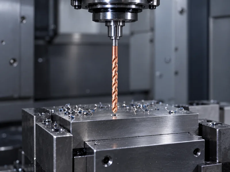
In a carbide drill equipped with internal coolant passages, through-tool coolant carries fluid toward the cutting zone and supports chip transport back along the flutes. The pump's pressure rating alone does not establish what reaches the drill. The holder connection, filters, coolant passages and available flow all affect delivery.
Pressure, flow and filtration requirements depend on drill diameter, material and the selected coolant passages. A blocked passage or leaking holder can interrupt delivery even when the machine display shows the expected pressure. This explains why a pressure reading at the pump can coexist with chip congestion at depth.
External coolant at the hole entrance may not reach the cutting edges at full depth. The differences in fluid access and machine requirements are covered in internal coolant versus external coolant carbide drills.
Continuous Drilling or Pecking: What Determines the Cycle?
Hole depth alone does not determine whether pecking is appropriate. Some solid carbide deep-hole drills are designed for continuous cutting under specified conditions; other tool and material combinations require a different cycle. Repeated re-entry changes how the edges contact the hole and any retained chips.
Chip shape provides evidence of what is happening inside the hole. Chips wrapped around the tool, material retained in the flutes or a load increase at a repeatable depth can indicate that evacuation is failing. Feed, cutting geometry, coolant delivery and material condition all influence the cause; retract distance addresses only part of that process.
Starting cutting data applies to a defined tool, material and diameter. The resulting chip form, hole measurements and edge condition show whether those conditions suit the actual setup. A load change at a repeatable depth is particularly useful because it can be compared with coolant access and features on the component drawing.
What Changes When Deep Hole Drilling Aluminum?
The aluminum alloy and condition affect chip formation and adhesion at the cutting edge. Adhered material changes the effective cutting geometry, while chips retained in the flutes can mark the hole wall or obstruct evacuation.
Aluminum applications call for attention to cutting geometry, flute surface and coating selection together. LANDUN offers aluminum-oriented options, but the configuration depends on the actual alloy and hole. Coating color alone does not identify the suitable tool or establish its machining performance.
Adhered material on the edges, tangled chips and scratches along the hole provide different clues to the problem. Lubrication at the cutting zone and the path for chips to leave the hole both influence these symptoms. In a casting, internal cavities and interrupted sections can also change engagement as the drill advances.
What the Failure Location Can Reveal
| Observed problem | Where to begin | What to record |
|---|---|---|
| Chipping or breakage near entry | Pilot compatibility, alignment, holder runout and entry sequence | Pilot dimensions, entry surface and moment of failure |
| Load rises as depth increases | Chip accumulation, coolant delivery and flute condition | Failure depth, chip form and coolant settings |
| Scratched hole wall | Retained chips, adhered material and tool damage | Scratch location, edge condition and material grade |
| Hole position or straightness outside tolerance | Entry alignment, guidance, runout and workholding | Measurement method and deviation along the hole |
| Damage at an intersection or exit | Interrupted engagement, exit geometry and programmed transition | Section drawing and location of the interruption |
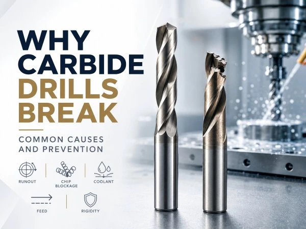
Breakage at the same depth may coincide with an intersecting hole or section change on the component drawing. Chip accumulation and loss of coolant access can also become apparent only after a particular depth. The location and timing of the fracture help distinguish these mechanisms from gradual wear. Other fracture patterns are discussed in why carbide drills break.
Which Details Help LANDUN Match a Drill to Your Hole?
A deep-hole inquiry is most useful when it describes the material grade and condition, hole diameter, full-diameter depth, tolerance and straightness requirement. Machine orientation, holder, coolant pressure and available flow, production quantity and any current failure symptoms help establish the machining conditions.
A section drawing shows features that dimensions alone can miss, including intersections, angled exits and special bottom forms. With this information in the inquiry form below, LANDUN can review a deep-hole drill configuration and its entry requirements. Holes outside the standard range can be discussed through a custom carbide drill inquiry.
Frequently Asked Questions
Is a 20xD drill's flute length the same as its usable drilling depth?
Not necessarily. The series designation, flute length and stated usable drilling depth describe different aspects of the tool. Match the required full-diameter hole depth to the selected model's usable-depth specification, including the allowance required for its point and chip clearance.
Can I use a spot drill instead of a pilot drill for deep holes?
Only if the long drill's application instructions permit that entry method. A spot establishes an entry feature but may not provide the diameter and depth needed to guide the long drill. Use the specified pilot geometry and entry sequence.
Should every deep hole be peck drilled?
No. Continuous cutting and peck cycles apply to different tool and material combinations. Use the selected drill's procedure rather than choosing a cycle from hole depth alone.
What coolant pressure should I use for a deep-hole carbide drill?
Use the pressure, flow and filtration specified for the drill diameter, material and depth. A pump pressure rating alone is insufficient because restrictions and leaks in the delivery path affect the supply at the tool.
 Need a Custom Tool solution?