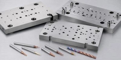
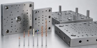
TOOL WEAR IN HARDENED DIE STEEL
MACHINING CHALLENGE
Punch plates, die plates, retaining plates, and hardened tooling components may cause rapid flank wear, cutting-edge chipping, rising spindle load, unstable hole diameter, or inconsistent tool life.
WHY IT HAPPENS
High material hardness, alloy content, heat-treated surfaces, local hardness variation, cutting heat, and unsuitable edge preparation can accelerate coating wear and cutting-edge damage.
LANDUN TOOLING RESPONSE
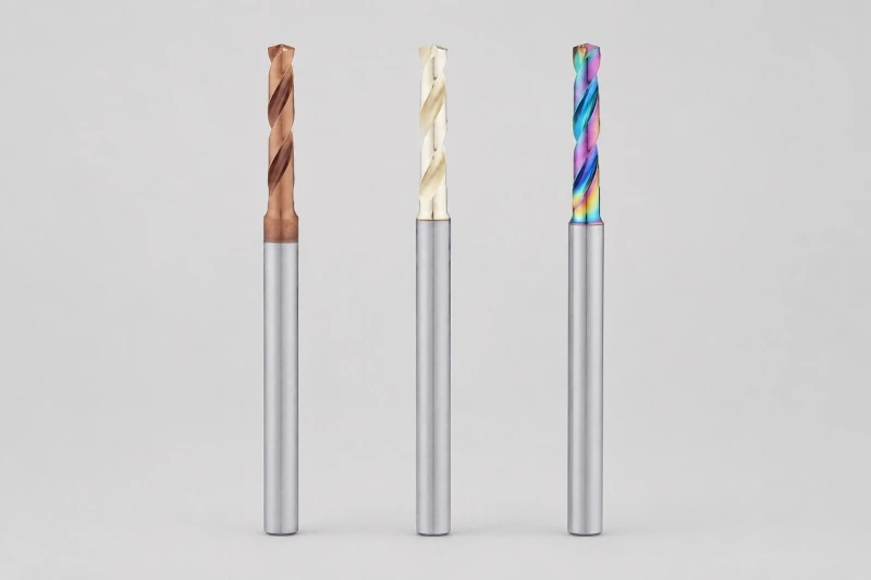
Wear-resistant coatings, controlled edge preparation, stable drill-point geometry, and suitable carbide grades help improve cutting-edge strength and tool-life consistency. Drill geometry should be matched to the material hardness, hole depth, coolant condition, machine rigidity, and production volume.
RECOMMENDED DRILL SERIES
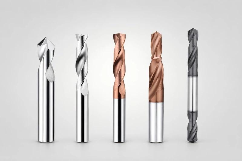
- Standard carbide drills for tool steel
- Internal-coolant carbide drills
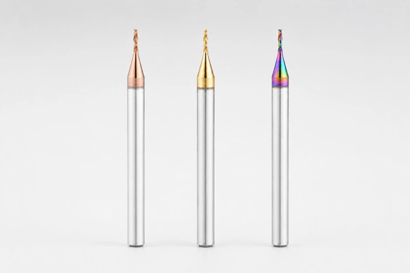
- Micro carbide drills for hardened materials
- Material-specific custom carbide drills
HOLE PATTERN ACCURACY ACROSS MATCHING PLATES
MACHINING CHALLENGE
Stamping-die assemblies often contain corresponding guide holes, dowel holes, mounting holes, punch-retaining holes, and bolt patterns across several matching plates.
WHY IT HAPPENS
Large plate dimensions, fixture movement, machine-positioning variation, uneven entry surfaces, spindle runout, and accumulated tool wear can affect hole spacing and alignment between related components.
LANDUN TOOLING RESPONSE
Stable drill-point geometry, rigid workholding, low-runout toolholding, and controlled tool wear help improve repeated-hole position consistency. Spotting may also be used where the surface condition does not provide reliable drill centering.
RECOMMENDED DRILL SERIES
- 3xD standard carbide drills
- 5xD standard carbide drills
- Carbide spot drills
- Custom drills for repeated hole patterns
CHIP EVACUATION IN THICK TOOLING PLATES
MACHINING CHALLENGE
Deep mounting holes, guide-related holes, punch-retaining holes, threaded-hole preparation, and through holes in thick tooling plates may experience chip congestion, rising cutting load, poor hole surfaces, drill deviation, or tool breakage.
WHY IT HAPPENS
Long drilling depth, limited flute capacity, insufficient coolant pressure, unsuitable drilling cycles, high runout, or chips remaining inside blind holes can interrupt normal chip evacuation.
LANDUN TOOLING RESPONSE
Through-tool coolant, suitable flute geometry, stable coolant pressure, rigid toolholding, and controlled drilling parameters help move chips away from the drill point. Longer holes may require an accurate pilot hole and controlled entry, drilling, breakthrough, and withdrawal.
RECOMMENDED DRILL SERIES
- 5xD and 8xD carbide drills
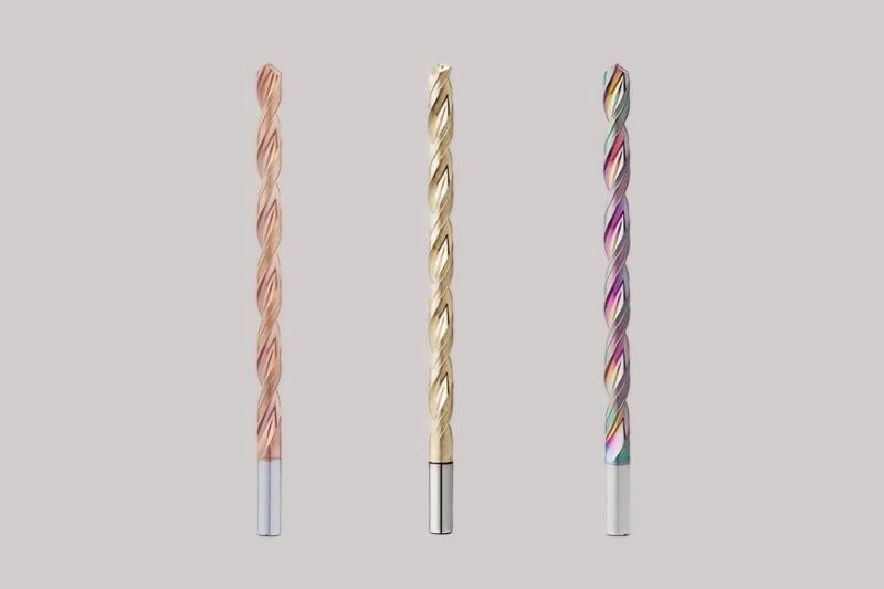
- 12xD and 15xD deep-hole carbide drills
- Internal-coolant carbide drills
- Custom long-reach carbide drills
GUIDE, DOWEL AND LOCATING HOLE STABILITY
MACHINING CHALLENGE
Guide-post holes, guide-bushing preparation holes, dowel holes, pilot-pin holes, and locating features require stable position, straightness, diameter allowance, and alignment between assembled die plates.
WHY IT HAPPENS
Uneven entry surfaces, inaccurate pilot holes, excessive runout, insufficient fixture rigidity, unsuitable drill length, and high cutting forces can cause drill walking or gradual hole deviation.
LANDUN TOOLING RESPONSE
Short and rigid entry tools, accurate pilot-hole preparation, low-runout holders, stable fixturing, and suitable point geometry help improve hole position and straightness. Controlled drilling allowance can also support subsequent reaming or boring operations.
RECOMMENDED DRILL SERIES
- Carbide spot drills
- 3xD and 5xD standard carbide drills
- Internal-coolant carbide drills
- Custom guide-hole preparation drills
STEP, FLAT-BOTTOM AND COMBINED HOLE ACCURACY
MACHINING CHALLENGE
Stamping-die components may require stepped holes, punch-retaining features, shallow counterbore-related holes, flat-bottom blind holes, locating shoulders, and combined drilling-and-chamfering operations.
WHY IT HAPPENS
Producing related features with several separate tools can introduce accumulated positioning errors, inconsistent depth, shoulder variation, excessive tool changes, and longer machining cycles.
LANDUN TOOLING RESPONSE
Step, flat-bottom, chamfer, and combination carbide drills can machine multiple related features in fewer operations. This helps improve concentricity, feature depth, shoulder position, and production efficiency.
RECOMMENDED DRILL SERIES
- Flat-bottom carbide drills
- Step carbide drills
- Carbide spot and chamfer drills
- Drawing-based custom carbide drills