DRILL ENTRY ON ANGLED AND CURVED SURFACES
MACHINING CHALLENGE
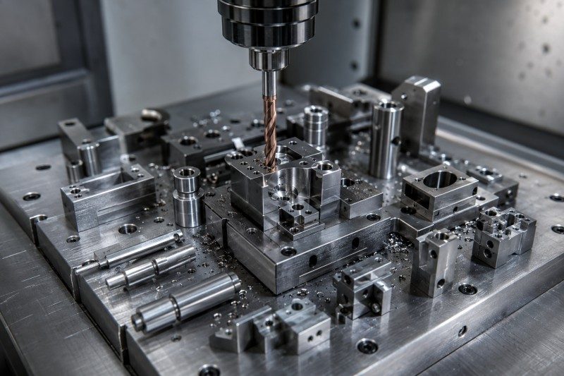
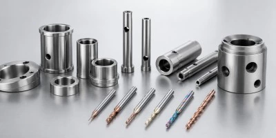
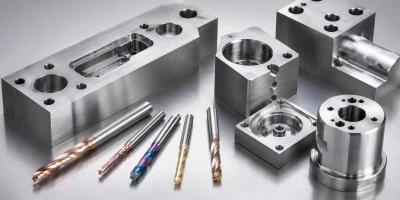
Sliders, lifters, sleeves, bushings, core pins, and compact insert components may require holes to begin on angled faces, curved surfaces, narrow bosses, drafted features, or partially interrupted areas..
WHY IT HAPPENS
Uneven initial contact creates unbalanced cutting forces. Excessive tool overhang, spindle runout, limited clamping rigidity, and unsuitable drill-point geometry can cause drill walking, deflection, edge chipping, or incorrect hole position.
LANDUN TOOLING RESPONSE
A short and rigid spotting operation, low-runout toolholding, stable workholding, and suitable drill-point geometry help improve initial positioning. Flat-bottom or custom-entry drills may be developed for strongly angled, curved, or interrupted surfaces.
RECOMMENDED DRILL SERIES
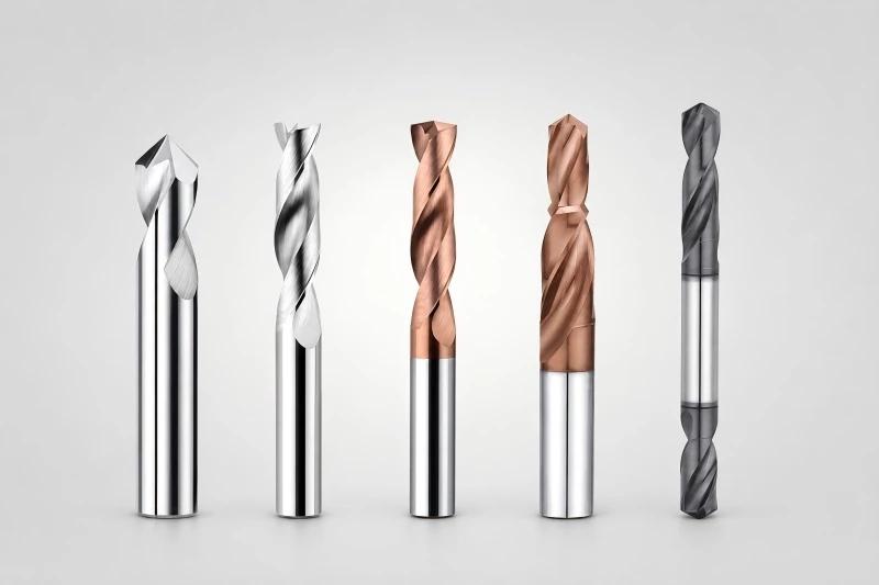
- Carbide spot drills
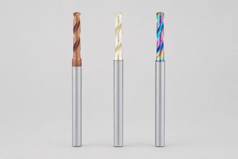
- 3xD standard carbide drills
- Flat-bottom carbide drills
- Custom drills for angled-entry features
SMALL-PART CLAMPING AND DEFORMATION CONTROL
MACHINING CHALLENGE
Small inserts, sleeves, bushings, sliders, and thin mold components may move, vibrate, distort, or develop exit burrs during drilling.
WHY IT HAPPENS
Limited clamping area, thin walls, uneven component geometry, excessive feed, long tool overhang, and unstable breakthrough can increase cutting-force concentration and local deformation.
LANDUN TOOLING RESPONSE
Rigid workholding, short tool overhang, sharp cutting geometry, controlled breakthrough feed, and low runout help reduce cutting forces and component movement. Custom drill geometry can be developed for thin-wall, hollow, or limited-support features.
RECOMMENDED DRILL SERIES
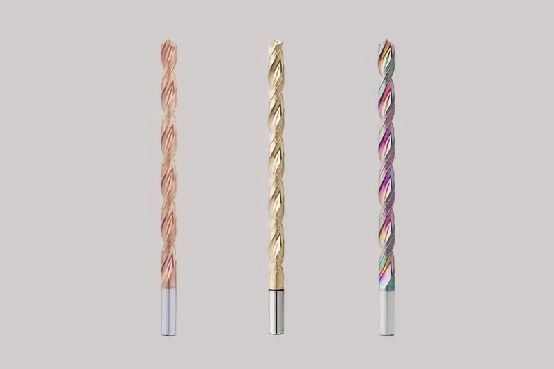
- Short standard carbide drills
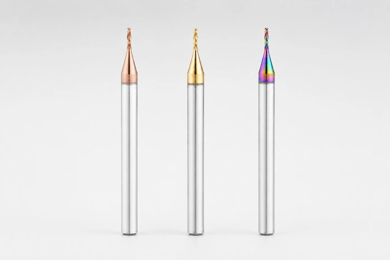
- Micro carbide drills
- Flat-bottom carbide drills
- Custom drills for thin-wall components
MICRO-HOLE STABILITY AND CHIP EVACUATION
MACHINING CHALLENGE
Vent holes, lubrication holes, small pin holes, fine cooling features, and compact passages may experience drill deflection, unstable diameter, chip packing, poor straightness, or premature micro-drill breakage.
WHY IT HAPPENS
Small-diameter drills are highly sensitive to spindle runout, excessive overhang, unstable entry, limited flute capacity, insufficient coolant delivery, and workpiece hardness.
LANDUN TOOLING RESPONSE
Low-runout toolholding, short overhang, stable point geometry, controlled cutting parameters, and suitable flute design help improve micro-hole reliability. Internal coolant or controlled drilling cycles may be considered for deeper small-diameter features.
RECOMMENDED DRILL SERIES
- 3xD micro carbide drills
- 5xD micro carbide drills
- Internal-coolant carbide drills
- Custom small-diameter carbide drills
STEP, FLAT-BOTTOM AND COMBINED FEATURE ACCURACY
MACHINING CHALLENGE
Precision mold components may require stepped holes, flat-bottom blind holes, counterbore-related features, locating shoulders, combined diameters, drilling and chamfering, or several connected hole features.
WHY IT HAPPENS
Producing these features with several separate tools can introduce accumulated positioning errors, inconsistent depth, concentricity variation, excessive tool changes, and longer machining cycles.
LANDUN TOOLING RESPONSE
Step, flat-bottom, chamfer, and combination carbide drills can machine multiple related features in fewer operations. This helps improve feature depth, shoulder position, concentricity, and production efficiency.
RECOMMENDED DRILL SERIES
- Flat-bottom carbide drills
- Step carbide drills
- Carbide spot and chamfer drills
- Drawing-based combination carbide drills
MATERIAL VARIATION AND CUSTOM TOOL REQUIREMENTS
MACHINING CHALLENGE
Precision mold components may be manufactured from hardened steel, stainless steel, bronze, copper alloy, aluminum, or other materials, while each component may contain different hole geometries and access restrictions.
WHY IT HAPPENS
Different materials require different cutting-edge sharpness, edge strength, flute finish, carbide grade, coating, and coolant conditions. A standard drill may not provide the required geometry, length, reach, or feature relationship.
LANDUN TOOLING RESPONSE
Material-specific geometry, application-matched coatings, polished flutes for non-ferrous materials, controlled edge preparation, and drawing-based custom designs help improve cutting stability and tool-life consistency.
RECOMMENDED DRILL SERIES
- Material-specific standard carbide drills
- Micro and internal-coolant carbide drills
- Special-length carbide drills
- Drawing-based custom carbide drills