
Medical fluid-control and diagnostic components contain cross holes, intersecting passages, distribution holes, valve ports, blind holes, deep channels, threaded-hole preparation, and small precision features.
Internal passages require reliable chip evacuation and controlled breakthrough, while valve, pump, and dosing components demand stable hole position, diameter, and sealing-interface accuracy. Small holes, limited chip space, thin sections, and difficult materials may also increase burr formation, drill deviation, tool wear, and blockage risk.
Landun CNC Tool provides standard and custom carbide drill solutions based on component drawings, materials, hole geometry, tolerances, coolant conditions, and production requirements.
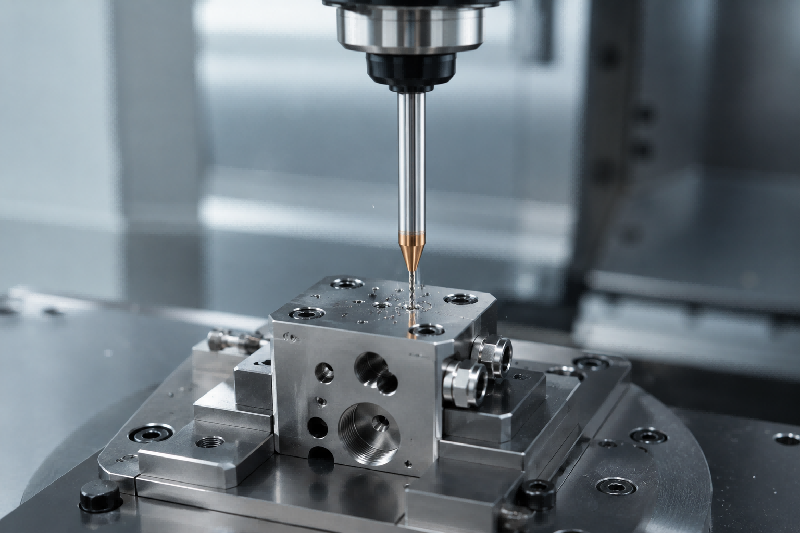
Valve bodies, pump components, fluid manifolds, and distribution blocks often contain cross holes and intersecting internal passages.
When a drill breaks into an existing hole, uneven cutting-edge engagement may cause impact, drill deflection, edge chipping, enlarged breakthrough areas, or inconsistent internal intersections.
One cutting edge may lose material support before the other as the drill enters an existing passage. Excessive feed, long tool overhang, high runout, unstable workholding, or unsuitable drill geometry can increase the resulting cutting-force imbalance.
Chips may also remain trapped at the passage intersection.
Rigid toolholding, low runout, controlled breakthrough feed, suitable point geometry, and stable component fixturing help reduce impact during cross-hole entry.
Internal coolant and planned drilling sequences can improve chip removal from intersecting passages. Special or custom drill geometries may be required for repeated cross-hole production.
Medical pump parts, dosing components, valve bodies, and compact fluid manifolds may contain deep blind holes, long distribution channels, or small-diameter internal passages.
These holes may experience chip congestion, cutting-heat accumulation, drill deviation, poor straightness, unstable hole depth, or premature drill breakage.
As the drilling depth increases, chips must travel farther through the flutes. Small diameters provide limited chip space, while insufficient coolant pressure, unsuitable drilling cycles, excessive runout, or poor machine rigidity can make chip evacuation unstable.
Packed chips may damage both the drill and the internal hole surface.
Internal-coolant carbide drills deliver coolant closer to the drill point and help move chips through long flutes.
Accurate pilot holes, suitable flute geometry, stable coolant pressure, controlled entry and withdrawal, and appropriate drilling cycles improve deep-hole stability and passage consistency.
Valve ports, pump interfaces, fluid connectors, threaded ports, sealing holes, and instrument fittings require controlled diameter, depth, concentricity, and surface condition.
Dimensional variation may affect component assembly, thread engagement, sealing performance, fitting position, or the relationship between connected passages.
Tool deflection, drill-point allowance, multiple tool changes, unstable entry, accumulated positioning error, or inconsistent depth control may affect the finished hole.
Curved, cast, or angled entry surfaces can further reduce drill-entry stability.
Spot drills improve entry position, while step, flat-bottom, chamfer, and combined custom drills can machine related features in fewer operations.
This helps improve feature concentricity, shoulder position, depth control, sealing-seat consistency, and threaded-hole preparation.
Dosing parts, diagnostic instrument components, sensor interfaces, precision nozzles, and compact fluid-control parts may contain small distribution holes or closely positioned precision features.
These holes may show diameter variation, hole-position error, unstable flow-related geometry, poor surface quality, or premature micro-drill breakage.
Small-diameter carbide drills have limited rigidity and are highly sensitive to spindle runout, holder condition, excessive working length, unstable clamping, incorrect parameters, and restricted chip evacuation.
Minor drill deflection can significantly affect small-hole size and position.
Precision-ground micro carbide drills, low-runout toolholding, short working lengths, stable fixturing, controlled feed, and reliable chip removal help maintain consistent hole dimensions.
Drill geometry, coating, flute design, and working length should be selected according to the material, diameter, and drilling depth.
Cross holes, distribution passages, thin-wall ports, small outlets, and intersecting channels may develop internal burrs, hanging chips, edge breakout, or material deformation.
These defects may interfere with fluid movement, assembly, downstream cleaning, or component inspection.
Unsupported breakthrough edges, worn cutting tools, excessive feed, unstable drilling conditions, poor chip evacuation, or unsuitable point geometry may deform material rather than cutting it cleanly.
Internal intersections are also difficult to inspect and deburr after machining.
Sharp cutting edges, controlled edge preparation, stable toolholding, suitable drill-point geometry, and reduced breakthrough feed help improve internal edge quality.
A planned machining sequence and custom tool geometry may reduce secondary deburring requirements on difficult internal features.
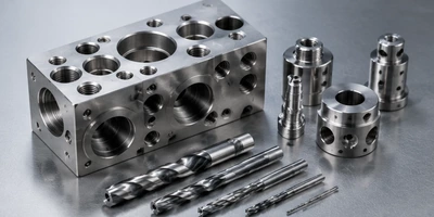
Typical components include valve bodies, compact manifolds, distribution blocks, cartridge interfaces, ported housings, and fluid-control components containing cross holes, blind passages, threaded ports, and intersecting channels.
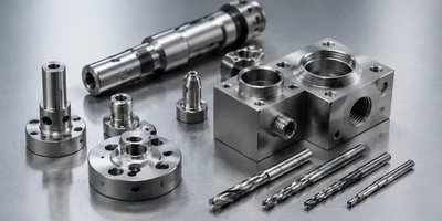
Common applications include pump bodies, dosing blocks, metering parts, piston-related components, compact chambers, nozzles, and fluid-delivery interfaces.
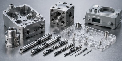
Typical components include diagnostic instrument housings, laboratory equipment parts, sample-handling blocks, sensor interfaces, mounting components, and compact fluid-routing parts.
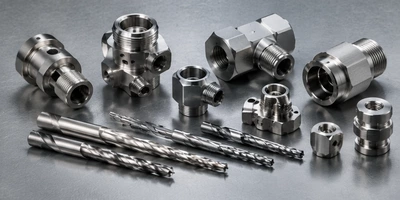
Common applications include fluid connectors, fittings, sleeves, bushings, adapters, distribution parts, and compact interfaces containing axial holes, cross holes, stepped holes, and sealing features.
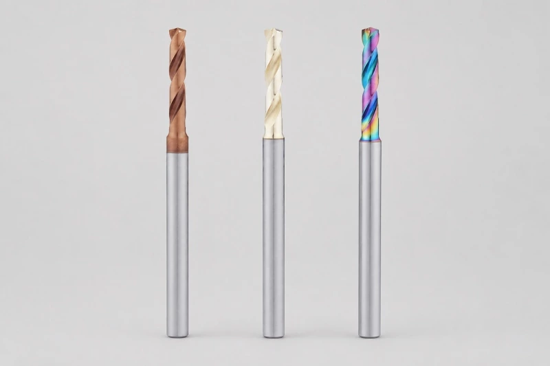
For general ports, mounting holes, locating holes, blind holes, through holes, and threaded-hole preparation in valve, pump, manifold, and diagnostic components.
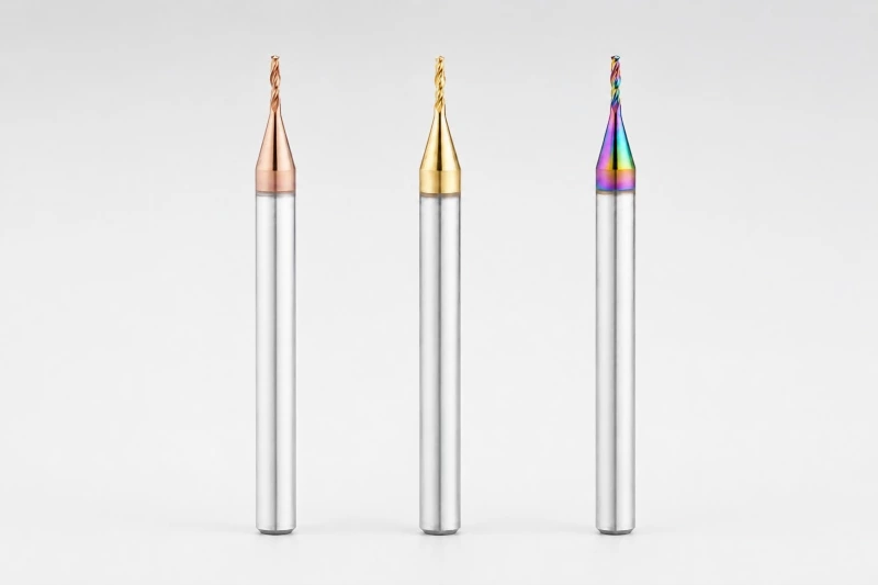
For small distribution holes, dosing holes, sensor-interface holes, outlet features, and precision passages requiring low runout and consistent dimensions.
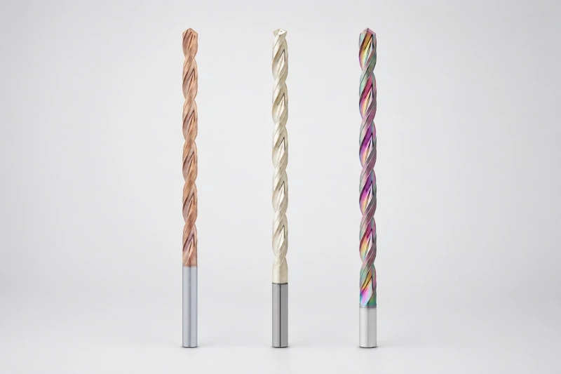
For valve bodies, manifolds, pump components, and distribution blocks containing deep blind holes, long fluid passages, or intersecting channels.
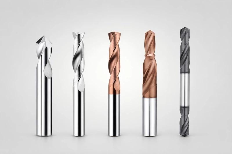
For cross holes, special diameters, stepped ports, flat-bottom holes, sealing features, combined operations, and drawing-based fluid-control components.
| INFORMATION | WHY IT MATTERS |
|---|---|
| Component drawing | Confirms hole geometry, entry angle, step features, tolerances, curved surfaces, and special requirements. |
| Workpiece material and hardness | Helps determine drill geometry, carbide grade, coating direction, edge preparation, and cutting parameters. |
| Hole diameter, depth, and type | Defines drill size, working length, depth-to-diameter ratio, and blind- or through-hole requirements. |
| Tolerance and surface finish | Helps evaluate dimensional accuracy, hole quality, and finishing requirements. |
| Machine, holder, and coolant conditions | Helps assess runout, rigidity, coolant pressure, and chip-evacuation stability. |
| Current problem and production target | Clarifies tool wear, burrs, chip packing, deviation, breakage, tool-life, or efficiency targets. |

Review the component drawing, workpiece material, hole structure, machine conditions, and current drilling problem.

Select a suitable standard drill series or develop a custom drill based on hole depth, tolerance, entry conditions, and machining requirements.

Produce the drill with controlled geometry, edge preparation, coating selection, and multi-stage inspection to support consistent quality.

Support sample testing, specification confirmation, and stable repeat production after the drill solution is approved.
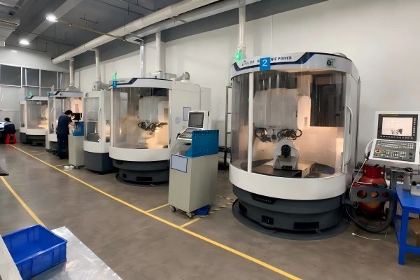
Walter 5-axis grinding supports stable drill-point geometry, flute consistency, diameter accuracy, and shank concentricity.
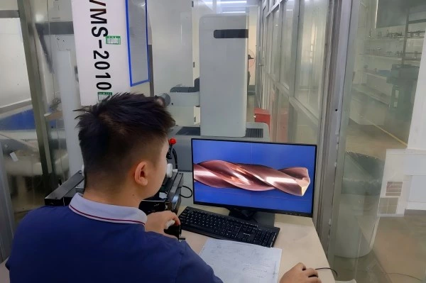
Controlled edge preparation helps improve cutting-edge consistency, coating adhesion, wear resistance, and tool-life stability.
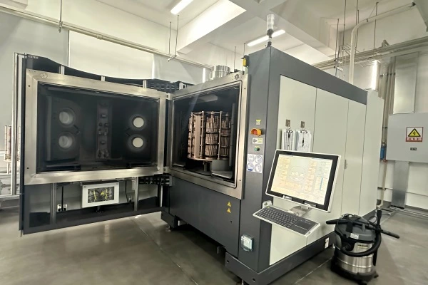
Coating selection is matched to the workpiece material and drilling conditions to improve wear resistance, heat control, and cutting stability.
HELICHECK PLUS and 150× / 300× visual inspection help verify dimensions, cutting edges, coating appearance, and overall tool condition.
We use cookies to collect information about how you use this site. We use this information to make the website work as well as possible and improve our services.more details