DIAMETER AND POSITION ACROSS REPEATED HOLE PATTERNS
MACHINING CHALLENGE
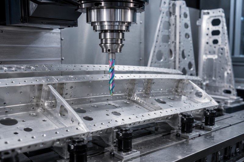
Aircraft skins, ribs, frames, stringers, brackets, and structural panels may contain large numbers of fastener, rivet, and assembly holes that must maintain consistent diameter, spacing, and position.
WHY IT HAPPENS
Large workpiece dimensions, fixture movement, uneven entry surfaces, spindle runout, accumulated tool wear, machine-positioning variation, and thermal changes can affect repeated-hole consistency.
LANDUN TOOLING RESPONSE
Stable drill-point geometry, low-runout toolholding, rigid component support, consistent edge preparation, and controlled tool-life management help improve hole-position and diameter repeatability. Spotting may be used where the entry surface does not provide reliable centering.
RECOMMENDED DRILL SERIES
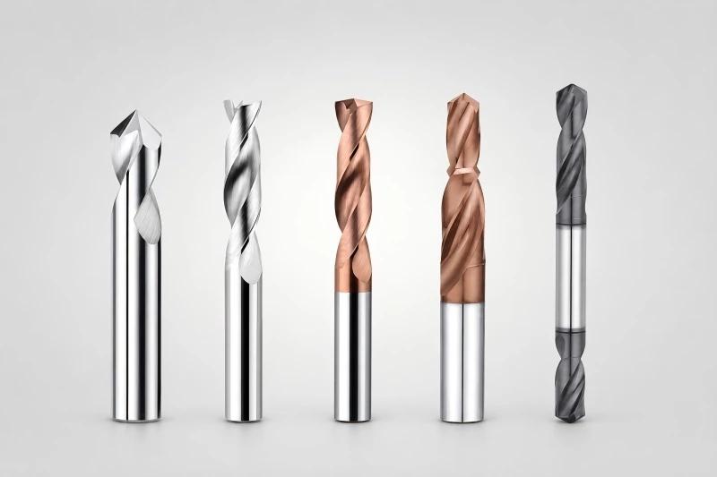
- 3xD standard carbide drills
- 5xD standard carbide drills
- Carbide spot drills
- Custom drills for repeated hole patterns
BURRS AND BREAKTHROUGH IN THIN-WALL STRUCTURES
MACHINING CHALLENGE
Aircraft skins, thin panels, ribs, brackets, and lightweight structural parts may develop exit burrs, edge tearing, local vibration, or deformation when the drill breaks through the material.
WHY IT HAPPENS
Thin sections provide limited support at the hole exit. Excessive feed, weak clamping, long tool overhang, unsuitable point geometry, or uneven remaining wall thickness can increase breakthrough force and reduce edge quality.
LANDUN TOOLING RESPONSE
Sharp cutting geometry, stable workholding, low runout, and controlled feed near breakthrough help reduce cutting force and exit burr formation. Application-specific drill points can also be developed for thin-wall and unsupported exit conditions.
RECOMMENDED DRILL SERIES
- Short standard carbide drills
- Carbide drills for aluminum alloys
- Flat-bottom carbide drills
- Custom drills for thin-wall breakthrough
CHIP CONTROL IN OVERLAPPING METAL SECTIONS
MACHINING CHALLENGE
Fastener and assembly holes may pass through overlapping skins, brackets, reinforcement plates, or metallic stack sections. Chips can become trapped between layers or remain inside enclosed structural areas.
WHY IT HAPPENS
Changes in material thickness, small gaps between assembled sections, interrupted cutting, unsuitable flute geometry, and insufficient coolant or air delivery can prevent chips from leaving the hole efficiently.
LANDUN TOOLING RESPONSE
Suitable flute geometry, controlled feed, stable chip formation, short tool overhang, and appropriate coolant or air delivery help improve chip evacuation. Custom geometry may be developed according to the material sequence, total stack thickness, and breakthrough conditions.
RECOMMENDED DRILL SERIES
- Standard carbide drills
- Internal-coolant carbide drills
- Short rigid carbide drills
- Custom drills for metallic stack structures
TOOL WEAR IN TITANIUM AND HIGH-STRENGTH MATERIALS
MACHINING CHALLENGE
Titanium attachment fittings, stainless brackets, high-strength structural joints, and reinforced assembly areas may cause rapid flank wear, edge chipping, rising cutting load, or unstable hole diameter.
WHY IT HAPPENS
Titanium and high-strength aerospace materials generate high cutting loads and concentrated heat. Low thermal conductivity, work hardening, material adhesion, and insufficient coolant delivery can accelerate coating wear and cutting-edge damage.
LANDUN TOOLING RESPONSE
Material-specific geometry, suitable carbide grades, controlled edge preparation, wear-resistant coatings, and stable coolant delivery help improve cutting-edge strength and tool-life consistency. Cutting parameters should be matched to the material, hole depth, and production volume.
RECOMMENDED DRILL SERIES
- Carbide drills for titanium alloys
- Carbide drills for stainless steel
- Internal-coolant carbide drills
- Material-specific custom carbide drills
FASTENER FIT, STEP AND PREPARATION-HOLE ACCURACY
MACHINING CHALLENGE
Close-tolerance fastener holes, bolt-hole preparation, pin holes, countersink-preparation holes, stepped holes, and assembly features may require stable diameter, depth, concentricity, and finishing allowance.
WHY IT HAPPENS
Repeated tool changes, drill-point allowance, tool wear, unstable entry, chips remaining inside the hole, and accumulated positioning errors can affect the final relationship between the drilled hole and later reaming, countersinking, or fastening operations.
LANDUN TOOLING RESPONSE
Stable drill geometry, controlled working length, consistent diameter control, and suitable preparation allowance help improve downstream assembly. Step, chamfer, and combination carbide drills can reduce tool changes and maintain the relationship between connected features.
RECOMMENDED DRILL SERIES
- Standard carbide drills
- Step carbide drills
- Carbide spot and chamfer drills
- Drawing-based preparation and combination drills