TOOL WEAR IN HEAT-RESISTANT ALLOYS
MACHINING CHALLENGE
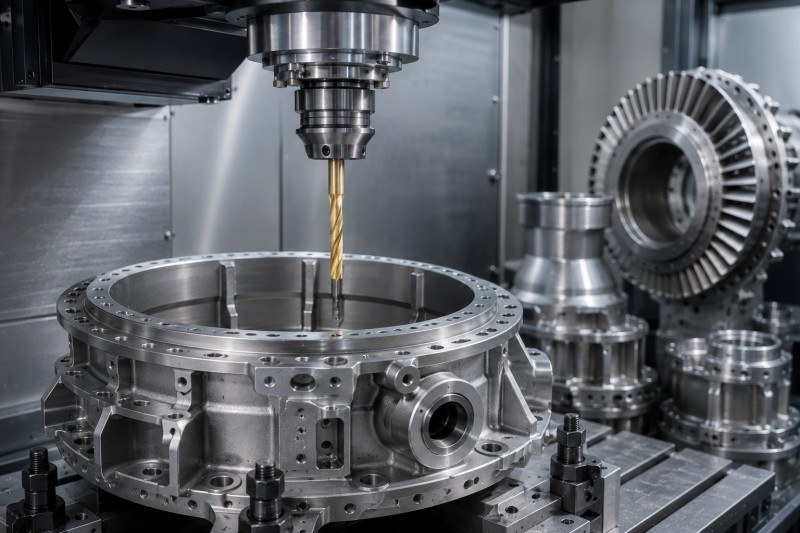
Compressor components, turbine housings, mounting rings, shafts, disks, and other engine parts manufactured from titanium, stainless steel, or nickel-based alloys may cause rapid flank wear, edge chipping, rising cutting load, and unstable tool life.
WHY IT HAPPENS
Heat-resistant aerospace alloys combine high strength with poor thermal conductivity. Cutting heat remains concentrated near the drill point, while work hardening, material adhesion, and high cutting forces accelerate coating wear and cutting-edge damage.
LANDUN TOOLING RESPONSE
Material-specific drill geometry, suitable carbide grades, controlled edge preparation, application-matched coatings, and stable coolant delivery help improve cutting-edge strength and wear resistance. Cutting parameters should be matched to the material grade, hole depth, machine rigidity, and production requirement.
RECOMMENDED DRILL SERIES
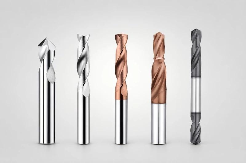
- Carbide drills for titanium alloys
- Carbide drills for stainless steel
- Internal-coolant carbide drills
- Material-specific custom carbide drills
CHIP EVACUATION IN OIL AND LUBRICATION PASSAGES
MACHINING CHALLENGE
Bearing housings, gearbox components, engine shafts, hubs, and propulsion housings may contain long oil-feed holes, lubrication passages, blind channels, and internal fluid paths that are prone to chip congestion.
WHY IT HAPPENS
Long drilling depths, limited flute capacity, high material strength, insufficient coolant pressure, excessive runout, or chips entering intersecting passages can interrupt chip evacuation and increase heat near the cutting edge.
LANDUN TOOLING RESPONSE
Through-tool coolant, suitable flute geometry, stable coolant pressure, rigid toolholding, and controlled drilling parameters help remove chips and reduce cutting heat. Longer holes may require an accurate pilot hole and controlled entry, drilling, breakthrough, and withdrawal.
RECOMMENDED DRILL SERIES
- 5xD and 8xD carbide drills
- 12xD and 15xD deep-hole carbide drills
- 20xD and 30xD deep-hole carbide drills
- Custom internal-coolant passage drills
ENTRY STABILITY ON CURVED ENGINE COMPONENTS
MACHINING CHALLENGE
Engine cases, shafts, disks, hubs, rings, and cylindrical housings may require drilling on curved surfaces, angled bosses, narrow flanges, cast surfaces, or partially interrupted areas.
WHY IT HAPPENS
Uneven initial contact produces unbalanced cutting forces. Excessive tool overhang, spindle runout, unstable clamping, or unsuitable point geometry can cause drill walking, deflection, incorrect hole position, or cutting-edge chipping.
LANDUN TOOLING RESPONSE
A short and rigid spotting operation, low-runout toolholding, stable fixturing, and suitable drill-point geometry help improve initial positioning. Flat-bottom or drawing-based custom drills may be used for strongly curved, angled, or interrupted entry conditions.
RECOMMENDED DRILL SERIES
- Carbide spot drills
- 3xD standard carbide drills
- Flat-bottom carbide drills
- Custom drills for curved or angled entry
INTERNAL BURRS AT CROSS-HOLE INTERSECTIONS
MACHINING CHALLENGE
Oil passages, lubrication channels, pressure holes, sensor ports, and other drilled features may intersect internal bores or existing passages, creating internal burrs, residual chips, or unstable breakthrough.
WHY IT HAPPENS
When a drill enters an existing passage, cutting support decreases suddenly and cutting forces become unbalanced. Excessive feed, unsuitable point geometry, insufficient coolant flow, or an incorrect machining sequence can increase burr formation.
LANDUN TOOLING RESPONSE
Controlled breakthrough feed, suitable drill-point geometry, stable entry direction, and through-tool coolant help reduce internal burrs and remove chips. Custom drills can be developed according to the intersection angle, wall thickness, passage diameter, and breakthrough condition.
RECOMMENDED DRILL SERIES
- Internal-coolant carbide drills
- Short standard carbide drills
- Micro carbide drills
- Custom cross-hole drills
BLIND, STEP AND CLOSE-TOLERANCE HOLE ACCURACY
MACHINING CHALLENGE
Aero engine components may require blind mounting holes, stepped ports, sensor holes, plug-hole preparation, flat-bottom features, combined diameters, and preparation holes for later reaming or boring.
WHY IT HAPPENS
Drill-point allowance, chips remaining at the hole bottom, repeated tool changes, unstable feed, and accumulated positioning errors can affect effective depth, shoulder position, concentricity, and feature consistency.
LANDUN TOOLING RESPONSE
Stable drill geometry, controlled working length, effective chip evacuation, and drawing-based combination tools help improve feature accuracy. Flat-bottom, step, and custom carbide drills can reduce tool changes and maintain the positional relationship between related features.
RECOMMENDED DRILL SERIES
- Flat-bottom carbide drills
- Step carbide drills
- Carbide spot and chamfer drills
- Drawing-based custom combination drills